Difference between revisions of "Exhaust Tutorial II"
| (12 intermediate revisions by the same user not shown) | |||
| Line 18: | Line 18: | ||
| − | ;3) | + | ;3) Designing Parts |
:*It is possible to create parts in the template and custom part interfaces, however, starting out this way tends to get confusing for new users of the software. It appears that there is a higher level of success with customers who start out designing parts directly in the assembly interface. | :*It is possible to create parts in the template and custom part interfaces, however, starting out this way tends to get confusing for new users of the software. It appears that there is a higher level of success with customers who start out designing parts directly in the assembly interface. | ||
| Line 148: | Line 148: | ||
==Creating an Offset Part== | ==Creating an Offset Part== | ||
| − | 1. Select the "'''New Section'''" button and place a length of pipe "'''24'''" inches long which runs directly through the | + | 1. Select the "'''New Section'''" button and place a length of pipe "'''24'''" inches long which runs directly through the rear axle at 6 inches parallel to the blue line. (See below.) |
| − | [[File: | + | [[File:exh_tut_offset99.png|center]] |
[[File:Exh_offset_steping1.png|right]] | [[File:Exh_offset_steping1.png|right]] | ||
| − | 2. Next, select the "'''Offset'''" [[File:Exhaust_offset1.png]] button, select the 2 foot section | + | 2. Next, select the "'''Offset'''" [[File:Exhaust_offset1.png]] button, select the 2 foot section in order to create an offset part that bends up and over the axle. |
| Line 161: | Line 161: | ||
| − | 3. Select the "'''3 Bends'''" option and select the "'''Next'''" [[File:Exhaust_next1.png]] button. | + | |
| + | 3. Select the "'''Next'''" button [[File:Exhaust_next1.png]] | ||
| + | |||
| + | |||
| + | |||
| + | |||
| + | |||
| + | |||
| + | |||
| + | |||
| + | |||
| + | |||
| + | |||
| + | 4. Select the "'''3 Bends'''" option and select the "'''Next'''" [[File:Exhaust_next1.png]] button. | ||
| + | |||
| + | |||
| + | |||
| + | |||
| + | |||
| + | |||
| + | |||
| Line 170: | Line 190: | ||
4. Since the section is 24 inches, type "'''12'''" in the "'''Distance to Center:'''" value field for the location of the center bend. | 4. Since the section is 24 inches, type "'''12'''" in the "'''Distance to Center:'''" value field for the location of the center bend. | ||
| + | |||
| Line 179: | Line 200: | ||
5. Select the "'''Next'''" [[File: Exhaust_next1.png]] button. | 5. Select the "'''Next'''" [[File: Exhaust_next1.png]] button. | ||
| + | |||
| Line 205: | Line 227: | ||
| − | 8. Type "''' | + | 8. Type "'''20'''" in the "'''Top Width: A'''" value field to establish the width of the offset. |
| Line 233: | Line 255: | ||
| − | |||
| − | |||
| Line 244: | Line 264: | ||
| − | |||
| + | 11. Name and save the offset specs to whatever you'd like. | ||
| Line 253: | Line 273: | ||
| + | 12. Select the "'''OK'''" [[File:OK_button1.png]] button. | ||
| − | |||
| − | |||
| − | |||
| − | |||
| − | |||
| − | |||
| − | |||
| − | |||
| − | + | '''The offset is now complete and should look like the first picture below.''' | |
| − | + | ==Creating Exhaust Pipes== | |
| − | + | 1. First, select the "'''New Section'''" [[File:Exhaust_newsec1.png]] button and fill in the remaining "'''6'''" inches from the offset part to the catalytic converter. | |
| − | [[File:Exh_define_offset8.png]] | + | [[File:Exh_define_offset6.png]][[File:Exh_define_offset8.png]] |
| − | + | 2. Working on the other side of the catalytic converter now, create 5 separate length segments as shown below. | |
| − | |||
| − | |||
| − | |||
| − | |||
[[File:Exh_define_offset11.png]] | [[File:Exh_define_offset11.png]] | ||
| Line 286: | Line 295: | ||
*Follow steps "'''1 - 11'''" of "'''Creating an Offset Part'''" to create an additional offset part that rises over the rear axle. | *Follow steps "'''1 - 11'''" of "'''Creating an Offset Part'''" to create an additional offset part that rises over the rear axle. | ||
| − | + | '''The part will then be complete.''' | |
| − | |||
| − | '''The part | ||
[[File:Exh_define_finished3.png]] | [[File:Exh_define_finished3.png]] | ||
Latest revision as of 12:39, 10 December 2014
This tutorial is designed to walk the user through the steps in making an exhaust system out of bent parts in the Exhaust interface. For initial and secondary assistance on the Exhaust interface, see Exhaust Design and Exhaust Tutorial.
Contents
Things To Know
- This tutorial is designed to walk the user through creating an exhaust system in the Exhaust Design interface. As you go through this tutorial, later procedures will assume that you understand all earlier procedures. Because of this, it is very important that you carefully step through this guide, understanding everything along the way and following all steps in order.
- A few key items need to be addressed before starting the step-by-step instructions of this tutorial. It is very important for Bend-Tech users to completely understand these items:
- 1) Center Line & Apex
-
- Center Line: In the Exhaust Design environment we are working exclusively with the center-line of a part, as compared to the inside or outside.
- 2) Locational Orientation
-
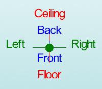
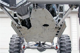
- Designing in the Exhaust Design interface seems to work the best if users imagine they are standing underneath the vehicle at a 45 degree angle, looking upwards. This way left is left and right is right. Take a minute and examine the Tri-Star to get your orientation.
- Notice how the vehicle in the picture is setup with the same orientation.
- 3) Designing Parts
-
- It is possible to create parts in the template and custom part interfaces, however, starting out this way tends to get confusing for new users of the software. It appears that there is a higher level of success with customers who start out designing parts directly in the assembly interface.
Start Up
1) Start by double clicking the "Bend-Tech 7x" icon to start up the program.2) Select the "Exhaust" icon ![]() in the Task Menu under the "Create New" section to open the Exhaust interface. The window that opens should be labeled [Exhaust Design – 1].
in the Task Menu under the "Create New" section to open the Exhaust interface. The window that opens should be labeled [Exhaust Design – 1].
3) For the purposes of this tutorial, click the "Maximize" button ![]() at the top right of the Exhaust Design window.
at the top right of the Exhaust Design window.
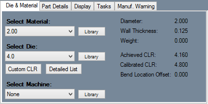
4) For the purposes of this tutorial. The "Die & Material" tab is located in the upper left corner of the window. Select the "2.00 Material" and "4.0 Die" as seen here.
Changing the "Grid Spacing"
1. Start by selecting the "Spacing:" value field and changing the value to "6".
- This will give the user more control and accuracy when creating their lengths of pipes in the display area.
2. Also, select the "Width:" value field and change the number to "240" to make our grid a complete square.
Creating an Axle
1. Select the "Axle" ![]() button and the "Add Axle" window will open.
button and the "Add Axle" window will open.
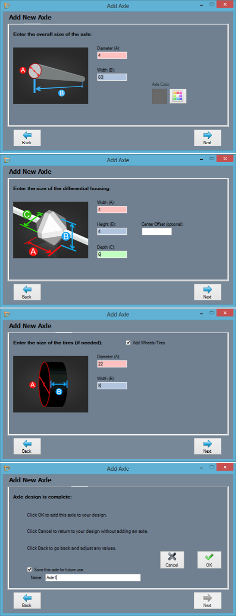
3. Type "4" in the "Diameter (A):" value field to set the axle diameter to 4 inches.
4. Type "60" in the "Width (B):" value field to set the distance from the axle's end to end.
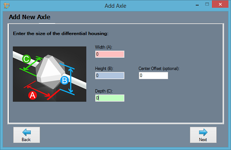
6. Type "4" in the "Width (A):" value field, "4" in the "Height (B):" value field, and "6" in the "Depth (C):" field to create the differential housing.
8. Select the check box that indicates that you'd like to add tires, type "22" in the "Diameter (A):" value field and "8" in the "Width (B):" value field to create tires on the axle.
10. Save the part as "Axle1" and select the "OK" ![]() button to finish the part.
button to finish the part.
11. Place the part in the display area as show here.
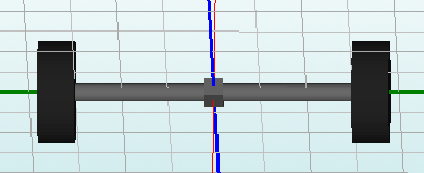
12. Now, create another axle without a differential housing by selecting the "Axle" ![]() button again and altering "Axle1".
button again and altering "Axle1".
13. Select the "Axle1" part form the saved axles list and click the "Next" ![]() button twice.
button twice.
14. Now, on the "differential housing" window, change all the values to "0" to make a duplicate of the saved axle without a differential housing.
15. Select "Next" ![]() until you reach the last window.
until you reach the last window.
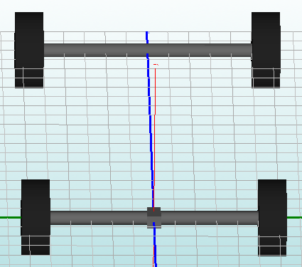
16. Select the "OK" ![]() button and place the axle exactly two spaces (12 inches) away from the edge of the grid as seen below.
button and place the axle exactly two spaces (12 inches) away from the edge of the grid as seen below.
Setting the Base
1. Select the "Set Base" ![]() button and click on the center of the new axle.
button and click on the center of the new axle.
Creating a Catalytic Converter
1. Select the "Cylinder" ![]() button and the "Add Cylinder" window will open.
button and the "Add Cylinder" window will open.
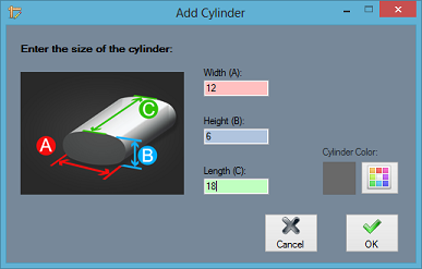
2. Type "12" in the "Width (A):" value field, and "6" in the "Height (B):" value field, "18" in the "Length (C):" field to create a cylindrical catalytic converter model.
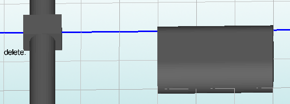
3. Select the "OK" ![]() button and place the part in the display area "6" inches to the left of the blue line and "14" inches behind the front axle(about 2 1/2 squares on the grid). (See picture below.)
button and place the part in the display area "6" inches to the left of the blue line and "14" inches behind the front axle(about 2 1/2 squares on the grid). (See picture below.)
Creating an Offset Part
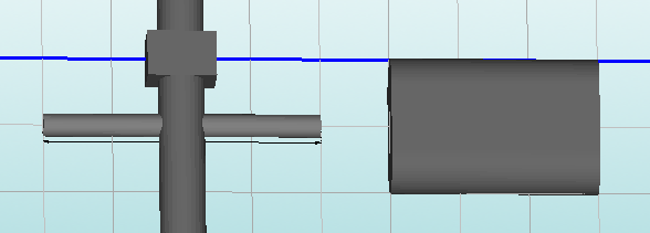
1. Select the "New Section" button and place a length of pipe "24" inches long which runs directly through the rear axle at 6 inches parallel to the blue line. (See below.)
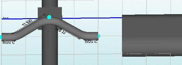
2. Next, select the "Offset" ![]() button, select the 2 foot section in order to create an offset part that bends up and over the axle.
button, select the 2 foot section in order to create an offset part that bends up and over the axle.
4. Select the "3 Bends" option and select the "Next" ![]() button.
button.
4. Since the section is 24 inches, type "12" in the "Distance to Center:" value field for the location of the center bend.
6. Type "6" in the "Vertical Offset(B):" to set the distance the center line of the part will move vertically off of it's plane.
8. Type "20" in the "Top Width: A" value field to establish the width of the offset.
10. Leave all the dies at "4.0" and select the "Next" ![]() button.
button.
11. Name and save the offset specs to whatever you'd like.
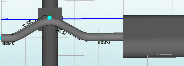
The offset is now complete and should look like the first picture below.
Creating Exhaust Pipes
1. First, select the "New Section" ![]() button and fill in the remaining "6" inches from the offset part to the catalytic converter.
button and fill in the remaining "6" inches from the offset part to the catalytic converter.
2. Working on the other side of the catalytic converter now, create 5 separate length segments as shown below.
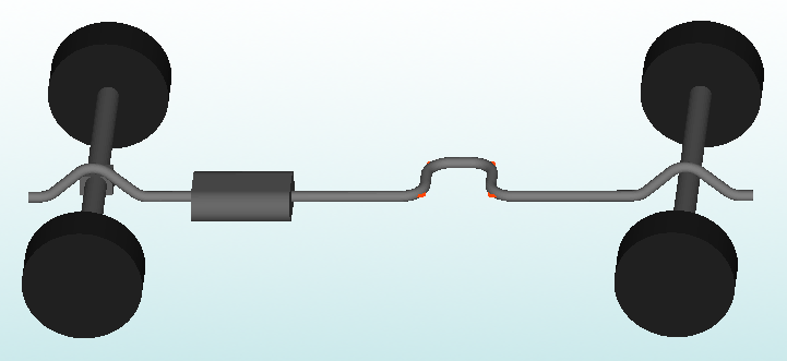
- Follow steps "1 - 11" of "Creating an Offset Part" to create an additional offset part that rises over the rear axle.
The part will then be complete.
- All part information will be held in the left hand corner in the "Defined Parts:" section.
- These parts can be transferred to other interfaces in order to play with bend angles, adjust lengths and so forth.
