Break Part
Bend-Tech 7x Wiki :: Break Part
Break Part allows part designs to be broken up into different pieces. This is typically done when the total length of the part exceeds the length of the longest tube/stock available.
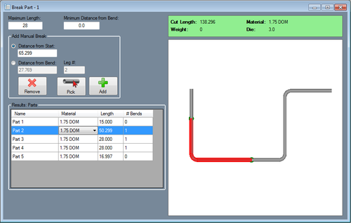
The longest tube length available and the required distance from each bend will be supplied. Breakpoints are placed along the part to define where the part will be separated. Then a chart of each individual part section with its material, length, and number of bends will be generated. From this chart, each part section can be exported to any of the part designers.
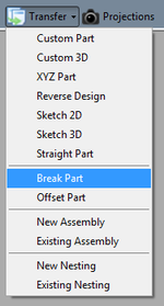
To access Break Part from assembly or any of the single part interfaces, click the Transfer menu at the top of the window and select the Break Part option. This will also bring in the current single part (if in a single part interface) or whichever part is currently selected in the Parts tab (if in assembly).
Maximum Length: This is the total length of the longest tube available. This length will determine how long each part section can be.
Minimum Distance from Bend: This is the shortest amount of material required on either side of a bend.
Once the longest tube length and bend distance have been supplied, default breakpoints will automatically be placed on the part. The part sections will be generated in the chart below. Default breakpoint locations will be based off the tube length and required bend distance.
Add Manual Break
Distance from Start: Enter the distance from the starting edge of the tube to define the location of the breakpoint. Once this value is entered, a purple point will be shown on the part to the right. This is a preview of where the breakpoint will be placed. To actually place the breakpoint, click the Add button. The breakpoint will turn green once it is placed. The chart will adjust to accommodate the new breakpoint.
Distance from Bend: Enter the bend that the breakpoint will be placed before in the Leg # field, then Enter the distance from the beginning of the length before the bend in the Distance from Bend field to define the breakpoint location. Once this value is entered, a purple point will be shown on the part model to the right. This is a preview of where the breakpoint will be placed. To actually place the breakpoint, click the Add button. The breakpoint will turn green once it is placed. The chart will adjust to accommodate the new breakpoint.
Pick: Breakpoints can also be placed by clicking on the part model. First, click the Pick button. ![]() Then click directly on the part to choose the breakpoint location. The breakpoint preview will be shown in purple. Both the From Start and From Bend fields will be filled in with the current breakpoint's location. These values can be edited to adjust the location of the breakpoint if necessary. To place the breakpoint, click the Add button.
Then click directly on the part to choose the breakpoint location. The breakpoint preview will be shown in purple. Both the From Start and From Bend fields will be filled in with the current breakpoint's location. These values can be edited to adjust the location of the breakpoint if necessary. To place the breakpoint, click the Add button.

