|
|
| Line 1: |
Line 1: |
| | '''[[Main Page|Bend-Tech 7x Wiki]] :: [[Main Menu Bar]] :: [[Tools]] :: Machine Library''' | | '''[[Main Page|Bend-Tech 7x Wiki]] :: [[Main Menu Bar]] :: [[Tools]] :: Machine Library''' |
| | + | __NOTOC__ |
| | | | |
| | + | [[File:machine_library_1.png|right|600px]] |
| | | | |
| − | '''View/Edit''': To view and/or edit a machine's information, first select the machine from the drop down menu at the top of the window. Once a machine is chosen, each tab below will show that specific machine's settings and defaults. Follow the instructions below to change any of these machine details.
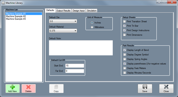
| + | [[File:machine_library_2.png|left|150px]]The Machine Library stores all machines that can be used to apply settings to single parts and for simulating the bending of a single part. Machines are defined by specifying the default die/material, result settings, rotation type, length/location type, output decimal tolerance, reverse design settings, and default simulation settings. |
| | | | |
| − | *Defaults: All settings in this tab are only defaults and can be changed, if necessary, after the machine is added to the part.
| |
| | | | |
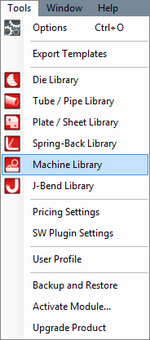
| | + | '''To access the machine library''', click on the '''Tools''' menu and select the '''Tube Library''' option in the drop down menu or click on the '''Tube Library''' option on the task menu. |
| | | | |
| − | To select a default die, click the drop down menu below 'Default Die' and select a die from the list.
| |
| | | | |
| − | To select a default material, click the drop down menu below 'Default Material' and select a material from the list.
| |
| | | | |
| − | To change the units the machine uses, click the circle next to 'Inches' or 'Millimeters'.
| |
| | | | |
| − | To add or change the machine's default note, enter a new note by typing in the field below 'Default Note'.
| |
| | | | |
| − | To adjust the default cut-off lengths, enter values into the 'Start End' and/or 'Far End' fields.
| |
| | | | |
| − | *Output Results: In the Output Results tab, the rotation type and scale, length/location settings, and tolerance levels for rotation angles, bend angles, and lengths can be set. The setup sheet and part results options are also available to choose here.
| |
| | | | |
| | | | |
| − | Under 'Rotation', either Incremental or Absolute can be chosen by clicking the circle next to the option. Incremental means the rotation angles will start at the end of the rotation before it. Absolute means the rotation angles will always start from the beginning of the rotation range at each new rotation. Below Incremental/Absolute, there is a list of rotation scales. Choose either -180 to 180, 180 to -180, 0 to 360, or 360 to 0 by clicking the circle next to the option.
| |
| | | | |
| − | Under 'Length/Location', the method of measuring the lengths of tube can be chosen. Choose either Distance from End, Distance from End- Reversed, or Length of Straight Tube by clicking the circle next to the option. If an index table is in use and there is any offset in between the machine and the table, the offset distance can be entered into the Offset Distance (Index Table) field.
| |
| | | | |
| − | Under 'Tolerance', the decimal tolerance for rotation and bend angle can be adjusted. To change either of these, select an option from the drop down menu below Rotation Angle or Bend Angle. Each 'n' represents a digit place.
| + | <h2>Defaults</h2> |
| | | | |
| − | Under 'Setup Sheets', printing options for the setup sheet can be adjusted. Check the box next to 'Print Transition Sheet' to print out a list of each movement (location, rotation, angle) made for each bend on the setup sheet. Check the box next to 'Print Tri-Star' to print the XYZ tri-star with the part image on the setup sheet. Check the box next to 'Print Design Instructions' to include the part results table on the setup sheet. Check the box next to 'Print Dimensions' to include the measurement lines and values on the part image on the setup sheet.
| + | <h2>Output Results</h2> |
| | | | |
| − | Under 'Part Results', settings specific to the results table can be adjusted. Check the boxes next to 'Display Length of Bend', 'Display Degree Symbol', and/or 'Display Spring Angles' to include any of these in the results table. Check the box next to 'Display parentheses () for negative values' to surround any negative values in the result table with parentheses.
| + | <h2>Design Input</h2> |
| | | | |
| − | *Design Input:
| + | <h2>Simulation</h2> |
| − | | |
| − | | |
| − | Under Reverse Design - Length, either Incremental or Absolute - Start, End, Center, Start (Reversed), End (Reversed), or Center (Reversed) can be selected by clicking the circle next to the option. This will determine how lengths will be measured when creating a Reverse Design part.
| |
| − | | |
| − | Under Reverse Design - Rotation, Incremental, Incremental - Reversed, or Absolute: 0 to 360, 360 to 0, 180 to -180, or -180 to 180 can be chosen by clicking the circle next to the option. This will determine how and on which scale the rotations will be measured when creating a Reverse Design part.
| |
| − | | |
| − | *Simulation:
| |
| − | | |
| − | | |
| − | To adjust the Travel, Rotation, Bending and/or Animation speed, click, hold and drag the pointer back and/or forth to adjust the speed level.
| |
| − | | |
| − | To choose the type of machine, click the drop down menu below 'Bender:' and select a machine type from the list.
| |
| − | | |
| − | To change the quality of the simulation, click the drop down menu below 'Quality' and select a quality level from the list.
| |
Bend-Tech 7x Wiki :: Main Menu Bar :: Tools :: Machine Library
The Machine Library stores all machines that can be used to apply settings to single parts and for simulating the bending of a single part. Machines are defined by specifying the default die/material, result settings, rotation type, length/location type, output decimal tolerance, reverse design settings, and default simulation settings.
To access the machine library, click on the Tools menu and select the Tube Library option in the drop down menu or click on the Tube Library option on the task menu.
Defaults
Output Results
Design Input
Simulation

