Offset Part
Bend-Tech 7x Wiki :: Offset Part
Parts can be sent to the Offset Part interface by using the Transfer menu ![]() and selecting the Offset Part option. New
and selecting the Offset Part option. New
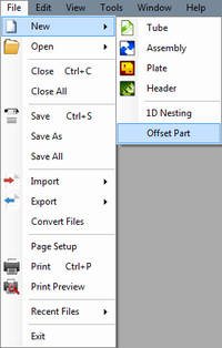
Straight lengths of tube can also be brought into this interface clicking the File menu, select New, then select Offset Part. The total length and material of this section will need to be defined first.
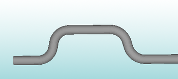
Offset Part allows offset sections to be added to completed parts. These offsets will appear similar to the section in the image shown below.
Material
The material used to create the current part can be chosen using the material menu. To choose a new material, click the material menu and select an option from the list. To view the Tube/Pipe Library, click the Library button.
Offset Style
There are two different types of offset available: 3 and 4 bend. See image below for what each of these offsets will look like.
Affected Section
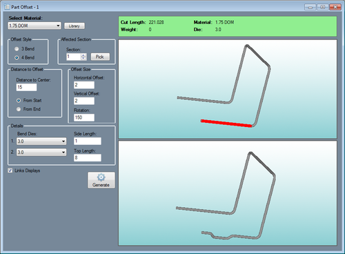
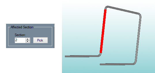
The section of the part where the offset will be placed can be chosen here. To choose a section, either enter a section number in the Section field or click the Pick button and select a section by clicking directly on it in the part display. The selected section will be highlighted in red.
Distance to Offset
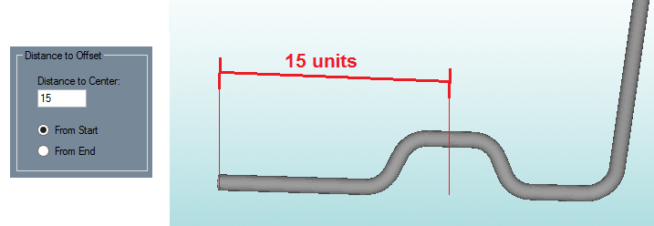
The offset's location can be defined as a distance from the start or end of the section to the center of the offset. Choose the starting point of the distance measurement (From Start or From End) and enter the distance value in the Distance to Center field. See image below for an example.
Offset Size
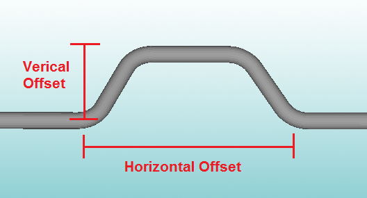
The size of the offset can be defined here. The Horizontal Offset is the distance across the length of the tube that the offset spans. The Vertical Offset is the distance between the section and the top of the offset section. See image below.
Details
- Bend Dies: If the offset is a 4 bend offset, the first die will be applied to the first two bends and the second die will be applied to the second two bends. If the offset is a 3 bend offset, the first die will be applied to the first two bends and the second die will be applied to the third bend. To select a die, click either of the Bend Dies menus and select a die from the list.
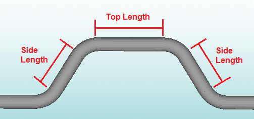
- Side Length: The side length is the length of the left and right "legs" of the offset. See image below.
- Top Length: The top length is only available for 4 bend offsets. This will be the length across the top of the offset. See image below.
Generate
Click the Generate button ![]() to generate a preview of the part with the offset section shown in the bottom display window. Check the Links Displays option to have the rotation of both part synchronized.
to generate a preview of the part with the offset section shown in the bottom display window. Check the Links Displays option to have the rotation of both part synchronized.
To send the part with the offset section to a part designer to get the bending instructions, to an assembly, etc. click the Transfer menu ![]() and select an option from the list.
and select an option from the list.
