Assembly

Due to its length, the Assembly Guide has a Table of Contents to accommodate the user.
The assembly interface allows a group of different bent and straight parts to be assembled together. Parts created in the single part designers (XYZ, Custom 3D, Sketch 2D, etc.) can be brought into assembly and parts within assembly can be transferred to single part designers. Parts can also be cut and the wrappers for these cuts can be printed out here.
To open a new assembly design:
1.) Go to the File menu, select New Assembly.
2.) Click the New Assembly icon ![]() at the top of the window.
at the top of the window.
...OR
3.) Select the Assembly option from the Task Menu that appears when the software starts up, when all designs are closed, or through the view menu.
Contents
Icon Toolbar
![]()
At the top of the frame just below the main menu bar, there is a series of icons.
Click the New Part icon ![]() to open the create new menu. This menu will allow you to choose a new part designer interface and begin a new part design.
to open the create new menu. This menu will allow you to choose a new part designer interface and begin a new part design.
Click the New Assembly icon ![]() to open a new assembly design.
to open a new assembly design.
Click the New Plate icon ![]() to open a new plate design. See the Plate page for further information on designing a plate.
to open a new plate design. See the Plate page for further information on designing a plate.
Click the New Header icon ![]() to open a new header design. See the Header Design page for further information.
to open a new header design. See the Header Design page for further information.
Click the Open icon ![]() to open a part, assembly, plate, or header file.
to open a part, assembly, plate, or header file.
Click the Save icon ![]() to save the current active window's progress. If the current window is a new and hasn't been saved previously, the part will need to be given a name and location. Click 'Save' in the Save window to save.
to save the current active window's progress. If the current window is a new and hasn't been saved previously, the part will need to be given a name and location. Click 'Save' in the Save window to save.
Click the Print icon ![]() to print out an image of the current view of the assembly design.
to print out an image of the current view of the assembly design.
Click the Print Preview icon ![]() to view a preview of the assembly design image print out.
to view a preview of the assembly design image print out.
Click the Solidworks icon ![]() to import a part file from Solidworks that has been sent to Bend-Tech.
to import a part file from Solidworks that has been sent to Bend-Tech.
Click the Display menu ![]() to alternate between a line or shaded part model.
to alternate between a line or shaded part model.
Click the Refresh icon ![]() to refresh the part display.
to refresh the part display.
Click the Home button ![]() to reset the 3D part display to its original default view.
to reset the 3D part display to its original default view.
Click the Zoom button ![]() to zoom all the way in on the current view of the 3D part display and fit it to the display frame.
to zoom all the way in on the current view of the 3D part display and fit it to the display frame.
Click on the Transfer menu ![]() to send the currently selected part in the Parts tab to any of the other part designers, a new assembly design, a new or existing Nesting project, the offset part interface, or the Break Part interface.
to send the currently selected part in the Parts tab to any of the other part designers, a new assembly design, a new or existing Nesting project, the offset part interface, or the Break Part interface.
Click on the Projections icon ![]() to view the current design from a specified plane (top, bottom, left, right, front, or back) or from a certain angle.
to view the current design from a specified plane (top, bottom, left, right, front, or back) or from a certain angle.
Tabs
![]()
A majority of the assembly features and functions are located in the tabbed section on the right hand side of the window. To find information about how to use these features, see the links below.
Main

Parts List
The Part List is a list of all parts that have been added to the current Assembly project. Select a part in the list to view a preview of it. The Qty (Quantity) column displays the number of times that the part is used in the current Assembly project and the Key column states the key number given to the part to identify it. To remove a part from the list, click the Remove button. ![]() To remove all unused parts from the Master Part List, click the Flush button.
To remove all unused parts from the Master Part List, click the Flush button. ![]()
Selected Part
Paste
To paste a copy of a part from the parts list into the assembly, first select a part. Then click the Paste button. ![]() The selected part will then be attached to the cursor. Select a PickPoint in the display to place the part upon.
The selected part will then be attached to the cursor. Select a PickPoint in the display to place the part upon.
Rotate

Creates a rotated version of an existing part which can be placed into the Assembly project.
Select a part from the Part List and click the Rotate button. ![]()
Select an axis to rotate the part around in the Select Axis of Rotation area.
Enter an amount to rotate the part in the Rotation Amount field, or left click on the part and drag the cursor left or right to rotate the part.
Enter a value in the Snap Increment field and check the Snap Rotation checkbox in order to use snap rotation. Snap rotation will rotate a part by the amount in the Snap Increment field when the part is rotated using the left mouse button.
To change the amount that the part is rotated when not using snap rotation, enter an amount in the Rotation Speed field. By default, the rotation speed will be 1, meaning the part will be rotated one degree at a time. Entering a decimal will allow the part to be rotated by smaller increments. Whenever you rotate a part in a certain axis, you must click the Apply Current Rotation button before rotating the part in another axis.
To reset the orientation of the part, click the Reset All button.
After all rotations have been applied, click the OK button.
Coupler

Allows the user to move the coupler (the anchor point of the part).
Select a part in the Part List and click the Coupler button. ![]() The Coupler Location window will appear.
The Coupler Location window will appear.
To set the reference point, click the Select Reference Point and click a PickPoint in the Coupler Location window display area.
To move the anchor point, use the Incremental Move fields and enter movement values.
To set all fields to 0 in the Incremental Move area, click the Clear Values button.
Click the Reset button to reset the coupler to its original location.
To toggle between viewing a shaded and wireframe version of the part, use the display mode options.
Mirror

Creates a mirrored version of an existing part which can be placed into the Assembly project.
Select a part from the Part List and click the Mirror button. ![]() The Mirror Part window will appear.
The Mirror Part window will appear.
In the Select Mirror Direction area, select an axis to mirror the part across. After a part has been mirrored, you must click Apply Mirror before mirroring the part again.
Click Reset Current to revert the part to the last time you clicked the Apply Mirror button.
Click Reset All to reset the part to its original orientation. Click the home button to set the display to the home view. Click OK to create the mirrored part.
To toggle between viewing a shaded and wireframe version of the part, use the display mode options.
Edit
To edit a plate part in the Plate design interface, first select a plate part from the Part List, then click the Edit button. ![]()
Open File
To open a part or plate part and use it in the current assembly design, click the Open Part ![]() or Open Plate button
or Open Plate button ![]() and select a part/plate file. The part will then be added to the Part List and attached to the cursor where it can be placed by clicking on a PickPoint in the part display.
and select a part/plate file. The part will then be added to the Part List and attached to the cursor where it can be placed by clicking on a PickPoint in the part display.
PickPoints
Single
Single Point
Click the Set Reference button ![]() and click a PickPoint to set it as the reference point.
and click a PickPoint to set it as the reference point.
- Normal Mode: Use the fields to enter the incremental distance from the Reference point that the new point will be.
- Travel Mode: Use the fields to enter the incremental distance from the reference point that the new point will be. Once the Apply button is clicked, this new point will automatically become the new reference point.
- Move Mode: This mode is used to move points. The selected reference point will be the point that is moved. Enter values into the fields to move this point using it's original location as the reference location. Note: This is the only function in the assembly interface that can be used to relocate PickPoints.
- Mirror Mode: While in mirror mode, all points placed will have a copy of the point mirrored across all axes.
Note: For easier navigation, notice how the harpoon fields axis rotates with the display frame and matches the orientation of the parts/points.
Click the Apply button ![]() to create the PickPoint. To reset all fields in the Single Point area to 0, click the Clear Values button.
to create the PickPoint. To reset all fields in the Single Point area to 0, click the Clear Values button.
Lines
Line (Two Points)
Creates a PickPoint that is aligned between two other PickPoints.
Click the Set Reference button and click two PickPoints or a single line.
In the Move Amount field, enter the distance from the first PickPoint that the new PickPoint should be. To measure the Move Amount distance from the other point, click the Swap Ends button. To set the new point directly in between the reference points click the Split in Half button.
To place the point, click the Apply button.
Intersection
Creates a point at the intersection of two user defined lines.
Click the Set Reference button and click on a line or the start point and end point of the first line. Click the start and end point of the second line. Check the Closest Intersection option to have the new point created at the intersection to become the reference point after it is created.
Click the Apply button to place a PickPoint at the intersection of the two lines.
String
Creates multiple points by specifying the quantity and spacing values.
Click the Set Reference button and click on a line or the start point and the end point of a line to define the reference points. Define the spacing between the points in the Spacing field and the number of points in the Quantity field. These points will begin at the starting end of the reference feature(s). To measure the points from the other end of the reference line, click the Swap Ends button.
Click the Apply button to place the PickPoints.
Plane/Arc
Plane
Creates a point by using a line and a plane for reference.
Click the Set Base Point button and click a PickPoint to set it as the center of the plane. Then select which axis the plane should lie on (X, Y, Z Plane or 3 Points). If 3 Points is selected, 3 PickPoints will need to be selected to define the custom plane.
Click two PickPoints, a line, or an arc to set them as the feature that the new line will be placed along. The new PickPoint will be at the intersection of the line and the plane. Click the Ignore Arc Ends to treat arc features as circles.
To move the new PickPoint up or down along the line, enter a value in the Move Amount field.
Click the Apply button to place the new point.
Arc
Creates a PickPoint by using an arc as reference.
Click the Set Arc button and click on an arc to select it. The angle of the arc should appear under Arc Angle in the Arc area.
Enter the angle along the arc that the new point should be in the Sweep Angle field. To set a point above or below the selected arc, enter a value in the Radius Offset field. Negative values will cause the PickPoint to be inside the arc. Click the Split in Half button to set the PickPoint halfway across the arc.
Click the Apply button to place the PickPoint.
Angle
Creates a PickPoint that is at a specified angle and distance from another PickPoint.
Click the Set Reference button and click on a PickPoint to set it as the reference point.
Use the Tri-Globe to select the direction of the new point. Enter an angle, using the Tri-Globe to determine which direction 0° and 90° are. Enter the distance from the reference point that the new point should be in the Length field.
Click the Apply button to place the PickPoint.
Alternatively, you can leave the Length and Angle field at 0 and use the two fields below the Length field to enter the distance from the reference point.
Note: For easier navigation, notice how the tri-globe rotates with the display frame and matches the orientation of the parts/points.
Edit Points
Change Color
To change the color of PickPoint(s), first select a color by clicking on the color block icon and choosing a color from the menu. Then click the Select Point(s) button and click on the point(s) in the display frame to change them to the newly select color.
To change the color of all PickPoints, first select a color by clicking on the color block icon and choosing a color from the menu. Then click the Change All button.
Display
Displays or hides PickPoints.
Click the Hide button ![]() and click a PickPoint to toggle if it is displayed or hidden.
and click a PickPoint to toggle if it is displayed or hidden.
Click the Display All button ![]() to display all PickPoints.
to display all PickPoints.
Click the Hide All button ![]() to hide all PickPoints.
to hide all PickPoints.
Delete Points
Click the Delete button ![]() and click on a PickPoint to delete it.
and click on a PickPoint to delete it.
Verify Points
Displays the coordinates of up to two PickPoints and their distance from each other.
Click the Verify Mode button ![]() and click on a PickPoint. Information on that PickPoint will be displayed. Click on a second PickPoint to see information on both PickPoints and their distance from each other.
and click on a PickPoint. Information on that PickPoint will be displayed. Click on a second PickPoint to see information on both PickPoints and their distance from each other.
Design
New parts can be drawn out using the Harpoon design interface or the LRA designer fields.
Edit

Move
Move Features
Click the Move Part button  to move full parts to new locations.
First, click on a PickPoint of a part. If Incremental Move is not checked, you will be asked to choose which PickPoint will be the anchor point. You will then be able to click any PickPoint to place the part there, with its anchor point centered on the point you select. If Incremental Move is checked, you will only have to click the part you are moving once. You will then be able to enter values into the Front, Back, Left, Right, Ceiling, and Floor fields in order to move the part in that direction by that value. To reset all fields to 0, click the Clear Values button.
To finalize and move the part to the new location, click the Apply button.
Click the Move Feature button  to move single features.
First, click a part and select a feature to move. If Incremental Move is checked, enter values into the Front, Back, Left, Right, Ceiling, and Floor fields and click the Apply button. If Incremental Move is not checked, click a PickPoint to move the feature there. The part will then be adjusted accordingly. See image below for an example of this function.

Move Bend
Click the Nudge Bend button  to push a bend a given amount in a specific direction.
Next, select the bend that will be adjusted. Use the green and pink directional buttons to slightly push the bend in a certain direction. The amount that the bend will be nudged is determined by the value in the Amount field, which can be adjusted by supplying a new amount.

Click the Move Bend button  to move a bend using the mouse controls.
First, select the bend to move. Next, the move bend tool will be placed upon this bend and can be used by clicking and dragging any of the arrows to pull the bend in a certain direction.

Adjust Radius
Click the Adjust Radius button  to increase/decrease the radius of a selected bend.
First, select the bend that will be adjusted. Then just click and drag the bend back and forth to adjust the radius.


Copy
Copy Single Part
Click the Select Part button ![]() to copy and paste a single part to a new location.
to copy and paste a single part to a new location.
First, select the part that will be copied. Next, choose a PickPoint to be the anchor point for the part. This point will be used as the "handle" to drag it to the new location. Last, click on the new location point to place the part.

Copy Multiple Parts
Use the Copy Multiple Parts tools to copy and paste a specified group of parts or points to a new location.
First, click the Set Base Point button ![]() to define the anchor point of the part/point group. This will be used as the point to attach the group to the new location point.
to define the anchor point of the part/point group. This will be used as the point to attach the group to the new location point.
Next, select the points or parts that will be copied by clicking on them. Once selected, a part/point will be highlighted in red. Be sure to specify which kind of features will be copied by choosing the Parts or PickPoints option. Click the Clear All button to clear all selections. Click the Select All button to select all of parts or points currently in the assembly design. Click the Complete button ![]() to indicate that all the desired parts have been selected.
to indicate that all the desired parts have been selected.
Last, click the Paste Parts button  and select the new location point to place the parts.
In order to paste the part or group of parts into another file or interface, open the new or existing file, go to the Edit-->Copy section and select the Paste Parts button and select the new location point to place the parts.


Rotate
Rotate is used to rotate current parts in the assembly design.
First, select the part to rotate by clicking the Select Part button ![]() and click on the part.
and click on the part.
Next, choose which axis the part will rotate about then click on a point on the part to define the rotation point.
Enter an amount to rotate the part in the Rotation Amount field, or left click on the part and drag the cursor left/right/up/down to rotate the part.
Enter a value in the Snap Increment field and check the Snap Rotation checkbox in order to use snap rotation. Snap rotation will rotate a part by the amount in the Snap Increment field when the part is rotated using the left mouse button.
To change the amount that the part is rotated when not using snap rotation, enter an amount in the Rotation Speed field. By default, the rotation speed will be 1, meaning the part will be rotated one degree at a time. Entering a decimal will allow the part to be rotated by smaller increments. Whenever you rotate a part in a certain axis, you must click the Apply Current Rotation button before rotating the part in another axis.
To apply the new rotation to the part, click the Apply button. ![]()

Mirror
The mirror function can be used to mirror parts in an assembly across a specified axis or a custom defined plane.
To do so, first click the Select Part button ![]() and click on a part in the assembly display frame.
and click on a part in the assembly display frame.
Next, choose an axis to mirror the part across. If the Plane (3 points) option is chosen, three PickPoints will need to be chosen in order to define the plane.
Check the Keep Original Part to treat the mirror as a copy. While this option is checked, the mirrored version of the part and the original part will remain in the design. Otherwise, the original part will be moved to the new mirrored location.
Click the Apply button ![]() to finalize the mirror.
to finalize the mirror.


Bent and straight parts can be deleted from the current assembly design in this tab.
To delete a part, first select a part by clicking on it in the list (listed parts will be highlighted in yellow once they are selected) or click directly on a part in the part display (parts will be highlighted in red once they are selected).
Click the Un-Select All button ![]() to un-selected all parts that are currently selected.
to un-selected all parts that are currently selected.
Click the Remove Selected button ![]() to delete the selected parts.
to delete the selected parts.

Stretch
Stretch moves a selection of PickPoints in a specified direction, adjusting all parts to compensate.
First select a view. This will determine which direction the assembly will be viewed from during the stretch process.
Select the parts/PickPoints that will be stretched by clicking on any two spots on the display in order to draw a selection rectangle between them (the rectangle will be defined by a light blue line).
Then select a direction and enter the amount that the selected parts/PickPoints should be moved in the Distance field.
Click the Apply button ![]() to apply the stretch.
to apply the stretch.


Misc
Add Bend
To add a bend to a preexisting part, click the Add Bend button ![]() and select a straight length of a part by clicking on it to choose a location for the bend. The bend will be placed at the mid point of the selected part length.
and select a straight length of a part by clicking on it to choose a location for the bend. The bend will be placed at the mid point of the selected part length.
Enter the offset distance between the part and the bend. Then click the OK button to place the bend. Whichever die is currently selected in the Assembly die menu will be used for this bend.

Scale
To scale the size of parts, material, or bend radii, click the Scale button. ![]()
In the scale window, scale values for each of these features can be supplied. Provide a percentage value to either increase or decrease the scale of a feature. See image below for an example.

Explode
Exploding an Assembly will move all parts away from each other so that they can be viewed separately.
First, click the Explode button. ![]()
The click on a PickPoint to set the base point for the assembly, and enter an explode factor to explode an Assembly project. Larger numbers will create greater distances between the parts. Click the Explode button to reset the assembly back to the normal display.
Clean
Click the Clean button ![]() to clear the assembly of any zero length tubes that may be in the assembly design.
to clear the assembly of any zero length tubes that may be in the assembly design.
Copy Radius
Click the Copy Radius button ![]() to copy the radius of one bend to another.
to copy the radius of one bend to another.
First, select the bend with the radius that you want to copy. Next, select the bend that the copied radius will be applied to.


Adjust Centerline
Click the Adjust Centerline button ![]() to change how the part measurements are interpreted. In the part designers, parts are assumed to be based on centerline. This tool allows the current part dimensions to be from the inside or outside of the tube instead.
to change how the part measurements are interpreted. In the part designers, parts are assumed to be based on centerline. This tool allows the current part dimensions to be from the inside or outside of the tube instead.
After clicking the button, select a part in the display to adjust it.
To change the Location and/or Location Type for a bend, first select the bend by clicking on it in the part display. A menu will appear where the location and location types can be adjusted. Click on either of the drop down menus to choose new options.

Once a new location or location type has been chosen, a red preview reflecting the location changes will appear. The original part will be shown in green (if the Display Original Part is checked).
Click the Home button ![]() to set the part preview to the default location and orientation.
to set the part preview to the default location and orientation.
Click the Zoom Fit button ![]() to zoom all the way in on the current view of the 3D part display and fit it to the display frame.
to zoom all the way in on the current view of the 3D part display and fit it to the display frame.
The part model can be shown in either wire frame or as a solid shaded model. Click on the wireframe button ![]() to show the model in wireframe. Click on the shaded button
to show the model in wireframe. Click on the shaded button ![]() to show the model as a shaded part.
to show the model as a shaded part.
Check the box next to Display Original Part to have the original part preview shown in the adjust centerline interface after changes are made to the locations.
Click the Inside button ![]() to set the locations for all of the bends to inside.
to set the locations for all of the bends to inside.
Click the Center button ![]() to set the locations for all of the bends back to centerline.
to set the locations for all of the bends back to centerline.
Click the Outside button ![]() to set the locations for all of the bends to outside.
to set the locations for all of the bends to outside.
Click the OK button ![]() to take the location and location type adjustments and apply them to the current part design.
to take the location and location type adjustments and apply them to the current part design.
Labels
To place labels on the current assembly design, first click the New button ![]() and select a location for the label by clicking on a PickPoint. Next, enter the label text and click OK.
and select a location for the label by clicking on a PickPoint. Next, enter the label text and click OK.

The size of the label font is determined by the Label Size value (larger values result in larger labels and vice versa). To change the size, enter a new value in this field. The color of the labels is determined by the Label Color button. To change the color, click this button and select a new color.
To move a label, click the Move button ![]() and select a new PickPoint to place the label in the new location.
and select a new PickPoint to place the label in the new location.
To delete a label, click the Delete button ![]() and click on a label.
and click on a label.
Break or Join Tubes
Click the Break Auto button ![]() to automatically break the part at a specified interval.
to automatically break the part at a specified interval.
First, define the maximum length of tube required between break points in the Max Length field. Next click the Break Auto button and select a part to break it.
Click the Break Point button ![]() to place a break point on a certain part. Break points will define where the part will be separated. After clicking this button, select which part will be broken by clicking on it in the display area. Last, select the PickPoint where the break will occur.
to place a break point on a certain part. Break points will define where the part will be separated. After clicking this button, select which part will be broken by clicking on it in the display area. Last, select the PickPoint where the break will occur.

Click the Join Tubes button ![]() to connect two tubes together. First, select the first part to join, and then select the other part that will be joined to it.
to connect two tubes together. First, select the first part to join, and then select the other part that will be joined to it.


Click the Miter Trim button ![]() to add a miter at the intersection of two tubes.
to add a miter at the intersection of two tubes.
First select the first tube that will be mitered. Next, select the other tube that will be mitered. These tubes will be given some extra length to compensate for the mitering cut (See image to the right). If the Create Cut option is checked, a cut will be applied to the part at this point on the part. Cuts can be seen in the Cutting tab.

Single Bend CLR Change
To adjust the CLR of a single bend, first select a die in the Select Die menu in the Single Bend CLR Change area. Next click the Select Bend button ![]() and click on a bend to apply the selected die to it.
and click on a bend to apply the selected die to it.


In the panel tab, plate panels can be created by defining their location on an assembly.
To create a panel, first click the Select Tubes button ![]() . Next, select sections of tube on the assembly that are on the same plane to define the outline of the panel (a minimum of 2 tubes is required). When selecting tubes, be sure to select the starting end of the tube. Once all the necessary tubes are selected, click the Complete button.
. Next, select sections of tube on the assembly that are on the same plane to define the outline of the panel (a minimum of 2 tubes is required). When selecting tubes, be sure to select the starting end of the tube. Once all the necessary tubes are selected, click the Complete button. ![]()

The parts will then be listed in the chart below. The corner and value specifications will need to be supplied for the corners and the wrap value will need to be given for the edges of the panel.
Once these values/options have been defined, click the Create Plate button. ![]() Give the panel and name and choose a plate material. Click the OK button to create the panel. Once a part is created, it is added to the parts list in the Main tab.
Give the panel and name and choose a plate material. Click the OK button to create the panel. Once a part is created, it is added to the parts list in the Main tab.
Click the Opposite Direction button to flip the side of the tube that the panel is placed upon.

To adjust the panel after it has been created, just change any of the options and click the Create Plate button to update the panel.
To do more in depth edits with the plate, such as adding holes, click the Edit Plate button to bring the plate into the Plate design interface. Once the edits are complete, the plate can be sent back into the assembly by using the Transfer menu ![]() and selecting the current assembly project. The plate will be brought back in and placed in its original location on the tube(s).
and selecting the current assembly project. The plate will be brought back in and placed in its original location on the tube(s).
Corner
- Connect: The corner of the panel will be flat, connecting the ends of the straight lengths on either side of the bend.

- Intersection: The corner of the panel will meet at the outside intersections of the tubes, at the apex.

- Radius: The corner of the panel will be rounded according the the radius value given in the Value field.

- Chamfer: The corner of the panel will be cut diagonally back from the corner the distance provided in the Value field.

- Notch: The corner of the panel will have a 90 degree notch cut out of it. The size of the notch is determined by the size provided in the Value field.

The Wrap value determines how far the material will overlap the edge of the tube. This value is given in terms of degrees.


Dimensions
Create
Single
Click the Single button  to place a single dimension. First, select a line feature or two points that the dimension will be placed between. Then choose a placement location for the dimension text.

Multiple
Click the Multiple button  to place multiple dimensions along a specified area of an assembly. First, select a line feature where the dimensions will start, then select end point of the dimensions. Between these features, each possible dimension will be placed.

Inside Angle
Click the Inside Angle button  to place an angle measure dimension at the inside of the intersection of two lines. First, select a line or reference point to represent the beginning of the dimension. Next, select the inside point of the line and/or the second reference line. Last, choose a location to place the dimension text.

Outside Angle
Click the Outside Angle button  to place an angle measure dimension around the outside angle of the reference lines. First, select a line or reference point to represent the beginning of the dimension. Next, select the inside point of the line and/or the second reference line. Last, choose a location to place the dimension text.

Edit
Move
Click the Move button  to relocate the text and marker of a dimension. First select the dimension that will be moved. Next, using the cursor, click on a new location to place the dimension.

Delete
To delete dimensions, click the Delete button  and click on a dimension(s) to delete them.
Settings
The appearance of dimension text and markers can be adjusted using these settings.
- Text Size: The size of the dimension text can be supplied here. Larger values will result in larger dimension font size and vice versa.
- Text Color: The color of the dimension text can be chosen here. Click the color button and select a color to adjust text color.
- Line Width: The width of the dimension markers can be given here. Larger values will result in thicker dimension lines and vice versa.
- Line Color: The color of the dimension marker lines can be chosen here. Click the color button and select a color to adjust line color.
- Tolerance: The decimal tolerance for the dimension values can be adjusted here. The decimal tolerance controls how many digits will be allowed after these values. In the tolerance options, each digit place is represented by an n.
- Dimension values can be displayed in either fractional or decimal format. To change the format and/or tolerance for lengths, click the drop down menu and select an option from the list.
- Display Dimensions: Check the box next to Display Dimensions to have the dimensions placed on the assembly design. Uncheck this box to hide the dimension markers and values.
2D Mode

In 2D Mode, the assembly will be shown from the top, left, and right. Dimensions can then be placed on these different views of the assembly. The display can be printed using File --> Print or by clicking the Print icon.
Create
- Horizontal: Click the Horizontal button
 to place a horizontal dimension along a selected line or between two selected PickPoints.

- Vertical: Click the Vertical button
 to place a vertical dimension on a vertical line or between two selected pickpoints.

- Linear: Click the Linear button
 to place a dimension along any line or between any two PickPoints.

- Inside Angle: Click the Inside Angle button
 to place an inside angle dimension at the intersection of two lines. First, select a line or reference point to represent the beginning of the dimension. Next, select the inside point of the line and/or the second reference line. Last, choose a location to place the dimension text.

- Outside Angle: Click the Outside Angle button
 to place an outside angle dimension around the intersection of two lines. First, select a line or reference point to represent the beginning of the dimension. Next, select the inside point of the line and/or the second reference line. Last, choose a location to place the dimension text.

Edit
Click the Move button  to relocate the text and marker of a dimension. First select the dimension that will be moved. Next, using the cursor, click on a new location to place the dimension.
To delete a dimension, click the Delete button  and click on a dimension.
Click the Edit Value button  to change the value of a dimension. First, click on a dimension. Then enter the new value in the edit value window and click the OK button.
Settings
- Arrow Width: This is the width of the arrows at the ends of the dimension line. Enter a value in this field to define the arrow width. Larger values will result in wider arrows and vice versa.
- Arrow Length:This is the length of the arrows at the ends of a dimension line. Enter a value in this field to define the arrow width. Larger values will result in longer arrows and vice versa.
- Extension Stand-Off: This is the distance between the extension lines and the entity that the dimension is measuring.
- Extension Offset: This is the distance that the extension lines extend beyond the dimension line.
- Text Size: The size of the dimension text can be supplied here. Larger values will result in larger dimension font size and vice versa.
- Line Width: The width of the dimension markers can be given here. Larger values will result in thicker dimension lines and vice versa.
- Arrow Type: This is the shape of the arrows at the ends of a dimension line. Click on the menu next to Arrow Type in the value column and select an option from the drop down menu.
- Tolerance: The decimal tolerance for the dimension values can be adjusted here. The decimal tolerance controls how many digits will be allowed after these values. In the tolerance options, each digit place is represented by an n.
- Dimension values can be displayed in either fractional or decimal format. To change the format and/or tolerance for lengths, click the drop down menu and select an option from the list.

- Text, Extension, and Dimension Color: The colors of the dimension text, extensions can be changed using these color options. To change the color of a feature, click on the corresponding button and select a color from the menu. (See the image to the right)
Edit Existing
Click the Select  button and click on a dimension to view and/or edit its settings, which will be generated in the Settings area above.
Click the Apply  button to apply any setting changes made to the currently selected dimension.
Click the Apply to All  button to apply the currently selected dimension settings to every dimension.
Cutting

The Cutting tab contains the tools necessary for adding cuts to the ends of parts. Wrappers can be printed which, when wrapped around the end of a tube, mark where the tube needs to be cut.
Make Cuts
Click the New Cut button ![]() and click a part. The cut part will be highlighted in green once selected. Click a second part, plane, or multiple parts that the first part will be cut to fit against. The second and any consecutive selected parts will be highlighted in red. Click the Complete button.
and click a part. The cut part will be highlighted in green once selected. Click a second part, plane, or multiple parts that the first part will be cut to fit against. The second and any consecutive selected parts will be highlighted in red. Click the Complete button. ![]() The cut should appear in the list of cuts on the Cutting tab and shown on the assembly.
The cut should appear in the list of cuts on the Cutting tab and shown on the assembly.

Click the Auto-Cut button ![]() to let the software attempt to generate all cuts in the assembly project.
to let the software attempt to generate all cuts in the assembly project.
Cutting Plane
Using the cutting plane feature, a custom plate can be defined and used to place cuts anywhere on the assembly design.
To place a cutting plane, click the New button ![]() and click on a PickPoint to define the center/base point of the plane. Then click the first direction and second direction of the plane. Once a plane is place in the assembly, it can be used as a cutting feature and will allow straight cuts to be placed anywhere.
and click on a PickPoint to define the center/base point of the plane. Then click the first direction and second direction of the plane. Once a plane is place in the assembly, it can be used as a cutting feature and will allow straight cuts to be placed anywhere.

To move the plane, click the Move button. Then click and drag the move tools directly on the plane to move, resize, and rotate the plane. See image below.

Slot & Tab
RESERVED FOR DRAGON CUSTOMERS ONLY.

Use the Slot & Tab function only after you have set up your Slot & Tab settings in the Tube/Pipe Library. Attempting to use this function without creating valid settings applied to your tubing will not produce results.
- Click the Slot & Tab
 button after you've created a cut and click on the green highlighted tube to apply the tab to it. This will also apply the slot to the outer edge of the red highlighted tube.
- If the tab & slot is not wide or long enough, you can always change the settings in your Tube/Pipe Library and then click the "Complete" button to apply the changes to the cut.

Cut Settings
If the Outside Diameter Only option is checked, the software will not display the inside diameter cut line for each cut. Using a hole saw requires the checking of the outside of the material only. "Check" the option "Outside Diameter Only".
![]()
Using a grinder or plasma cutter requires checking of both sides of the material. "Uncheck" the option "Outside Diameter Only".
![]()
If Distance to Perp of Bend is checked, the red line will indicate the distance to the perpendicular of the bend. The cut wrapper's red line will display the distance to the tangent of the nearest bend combined with the outside radius of the bend.
If the Hide Completed Features option is checked, completed features from the new cut will be hidden in the design.
If the Ignore Tube Ends option is checked, all new cuts will ignore the excess tubing leftover from all other cuts.
If Mitered Cut is checked, all new cuts will be calculated as straight mitered cuts. If you are using a hole saw to cut your tubes leave Mitered Cut unchecked.
If the Add Slot & Tab checkbox is checked, all new cuts will contain a tab on the intended cut tube and a slot on the adjoining tube. Adding a value into the value field to the right will rotate the tab around the tube by a degree between 0-360.
Cut Chart

A chart displaying a list of all the cuts currently applied to the assembly will be shown as well.
Click on a cut to see a preview of the cut on the 3D model of the assembly.
Click Delete ![]() to remove the cut from the tube, or click Delete All
to remove the cut from the tube, or click Delete All ![]() to remove all cuts from the Assembly project.
to remove all cuts from the Assembly project.
Click Print ![]() to print the currently selected wrapper, or click Print All
to print the currently selected wrapper, or click Print All ![]() to print out all wrappers for the entire Assembly project.
to print out all wrappers for the entire Assembly project.

Click the Details button ![]() to see a preview of the cutting wrapper. On each wrapper, there is a red line with a number on it. This line is used for lining up a wrapper on a tube. The number is the distance from the end of the tube that the red line should be.
to see a preview of the cutting wrapper. On each wrapper, there is a red line with a number on it. This line is used for lining up a wrapper on a tube. The number is the distance from the end of the tube that the red line should be.
Click the Select button ![]() and click on a cut in the display area to select it from the assembly directly.
and click on a cut in the display area to select it from the assembly directly.

Parts
The Parts tab contains a list of all parts in the current Assembly project, tools that can be used to edit them, and the ability to transfer parts to a single part designer.
Click on a part in the part list to select it. Once a part is selected in the list, it will be highlighted in yellow. Parts can also be selected by clicking directly on a part in the assembly.
Use the drop down menu in the Die column to change the die for that part or use the drop down in the Material column to change the material.
Click on the colored box in the Color column to change the parts color using the color menu.
Select a part and use the Transfer menu ![]() to bring it into another part design interface.
to bring it into another part design interface.
Double click on this table to open it in a separate window. Click the Print button to print this chart.

Details

In the details tab, a list of every material used in the assembly project will be listed along with the material's attributes, such as the name, width, amount used, and weight.
If weight per unit values have been given to the materials in the Tube/Pipe Library, the total weight of the assembly will be shown below the table.
Change Die or Material
Click the All Dies button ![]() to change all the dies used in the assembly to one specified die. After clicking the button, select a die from the menu and click the OK button to confirm the die change.
to change all the dies used in the assembly to one specified die. After clicking the button, select a die from the menu and click the OK button to confirm the die change.
Click the Match Die button ![]() to replace all bends using a certain die with an alternate die. In the menu, select the die that will be replaced and selected the die that will replace it. Click the OK button to confirm.
to replace all bends using a certain die with an alternate die. In the menu, select the die that will be replaced and selected the die that will replace it. Click the OK button to confirm.
Click the All Materials button ![]() to change all the materials used in the assembly to one specific material. After clicking the button, select a material from the menu and click the OK button to confirm the material change.
to change all the materials used in the assembly to one specific material. After clicking the button, select a material from the menu and click the OK button to confirm the material change.
Print Details
Click the Spreadsheet button ![]() to print out a page with an image of the 3D assembly model, the parts list, the chart shown in the Parts tab, and the material chart shown in the Details tab.
to print out a page with an image of the 3D assembly model, the parts list, the chart shown in the Parts tab, and the material chart shown in the Details tab.
Click the Setup Pack button ![]() to print out multiple setup sheets for the parts in the current assembly. In the Setup Pack menu, the printing options can be selected.
to print out multiple setup sheets for the parts in the current assembly. In the Setup Pack menu, the printing options can be selected.

- Select Features to Print: Select what kind of features will be included on the setup sheet.
- Select Printer: Choose the printer that the setup sheets will be printed from.
- Select Parts to Print: Choose which part setup sheets will be included in this printing. Click the Check All button to select all parts. Click the Check None button to un-check all parts.
Click the OK button to print the setup sheets.

Click the Full Scale button ![]() allows a full size, to scale, 2D version of the assembly design viewed from a specific direction to be printed to scale on multiple sheets. Each printed page will display one section of the full size assembly. When these pages are all combined, they will show the entire part design.
allows a full size, to scale, 2D version of the assembly design viewed from a specific direction to be printed to scale on multiple sheets. Each printed page will display one section of the full size assembly. When these pages are all combined, they will show the entire part design.
Adjust the settings explained below and click the Print button to print out a full scale part outline.
- Margins: The margins of each individual page can be set here in terms of inches.
- Default Orientation: The orientation of the pages can be adjusted here by choosing either portrait or landscape.
- Number of Pages: The width and height of the block of pages can be adjusted here. A preview of what the full group will be shown below. Each page is represented by a light blue outline.
- Line Width: The width of the line representing the part features can be adjusted here. Smaller values will result in thinner lines while larger numbers will result in thicker lines.
- Orientation: The angle that the part printout will be viewed from can be chosen here.
- Position... : To reposition the part outline on the pages, click the Position... button.
 The part outline will be attached to the cursor. Click to place the part in a new location. Keep in mind, if any of the part extends past the edge of the pages,
- Print Options:
- Select Printer: Choose which printer to print from here.
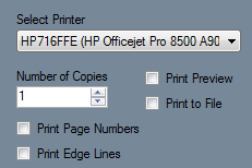

Number of Copies: The number of copies to print can be specified here.
Print Preview: Check this box to have a preview of the pages shown before it is printed.
Print to File: Check this box to save the pages as a Printer File (.prn).
Print Page Numbers: Check this box to print page numbers on each page.
Print Edge Lines: Check this box to include the margin lines on the pages.
- Preview: At the bottom of the window, a preview of the part outline and the pages will be shown.
- This preview can be adjusted by zooming, panning, and rotating. To zoom, use the scroll wheel on the mouse. Scroll up to zoom out and scroll down to zoom in. To pan/move the part preview, click and hold the scroll wheel or both mouse buttons and move the cursor around. The part preview will move with the cursor. To rotate, click and hold the right mouse button. Move the cursor around and the part will rotate with the cursor movements.
Assembly Tools
Click the Nesting button ![]() to
to

Click the Price button ![]() to view a chart containing the assembly's materials, quantity, and cost and time. These cost settings can be set up in the Tools Menu under Pricing Settings.
to view a chart containing the assembly's materials, quantity, and cost and time. These cost settings can be set up in the Tools Menu under Pricing Settings.
To add another column that will calculate the price for a specified amount of the part, enter a value into the Quantity First Field area or adjust the amount using the up and down arrows. Up to two extra columns can be added.
To add a second column, enter a value into the Quantity Second Field or adjust the amount using the up and down arrows.
To print the current view of the Price List chart, click the Print button. ![]()
Assembly Menu
When a new assembly window is open, there will be a menu area located above the tabbed section and display frame.

Material
![]() In the material menu, the material for the parts in the assembly can be selected. To select a material, click the drop down menu and choose a material from the list. This material can be changed for each individual part later, this is just the material that is initially applied to new parts. Tube/pipe materials are defined in the Tube/Pipe Library.
In the material menu, the material for the parts in the assembly can be selected. To select a material, click the drop down menu and choose a material from the list. This material can be changed for each individual part later, this is just the material that is initially applied to new parts. Tube/pipe materials are defined in the Tube/Pipe Library.
Die
![]() In the die menu, the die used to bend the parts in the assembly can be selected. To select a die, click the drop down menu and choose a die from the list. This can be changed for each individual part later, this is just the die that is initially applied to new parts. Dies are defined in the Die Library.
In the die menu, the die used to bend the parts in the assembly can be selected. To select a die, click the drop down menu and choose a die from the list. This can be changed for each individual part later, this is just the die that is initially applied to new parts. Dies are defined in the Die Library.
Straight
To create a straight tube between two PickPoints, click the Straight button  and click any two PickPoints or Auto points (points that are automatically generated along parts, such as mid points, apex point, or start and end of bend points ) in the display window.
Bent
To create a new bent part, click the Bent button.  In the Number of Bends window that appears, enter the number of bends that the part will have and click the OK button. To create the part, you must select the start point and the location of each bend, and the end point of the part. You cannot create a bend that is 180° or more by using the Bent Part tool. In order to create such a bend, you would need to create two separate parts.
Delete
To remove a part from the assembly, first click on the Delete button. Then in the design frame, click on a part to delete it.

Entities
The Entities tool controls which parts and points are displayed in the assembly. Click the Entities button  to open up this menu. Each row will represent straight part, bent part, and PickPoint. To hide a certain feature, click in the green box to remove the X. To have all features shown, click Display All button.
 ![]() To hide all PickPoints, click the Hide Points
To hide all PickPoints, click the Hide Points ![]() button. To hide all parts, click the Hide Parts button.
button. To hide all parts, click the Hide Parts button. ![]()
Bend Mode

This option controls the type of bend location for the very next bend-point selecting during the creation of a bent part. In other words, this setting will only affect the part being built. After selecting a bend-point, this setting will revert back to APEX, meaning you will need to select the right setting for each bend-point in the part (unless the points are APEX).
The type selected under this menu indicates what the bend-point represents:
Apex: The bend-point is the apex of the bend, which is the intersection point of the two legs on either side of the bend.
Tangent (Start): The bend-point is at the very start of the bend; where the straight leg meets the bend. (no bent material will be included in the measurement)
Tangent (End): The bend-point is at the very end of the bend; where the bend meets the straight leg. (no bent material will be included in the measurement)
Perpendicular (Start): The bend-point is at the perpendicular point on the first leg (start side). See image below. This location can also be measured as the start of the bend plus the radius; along the first leg.
Perpendicular (End): The bend-point is at the perpendicular point on the second leg (end side). See image below. This location can also be measured as the end of the bend plus the radius; along the second leg.
Mid: The bend-point is the exact mid point of the bend (middle of the bend).
Direction -> Any Point: This option requires the selection of TWO bend-points for a single bend. The first bend-point represents a location on the first leg of the bend (before the bend). This point can be located anywhere on the leg. The second point represents a location on the bend. This point can be located anywhere on the bend.
Any Point -> Direction: This option requires the selection of TWO bend-points for a single bend. The first point represents a location on the bend. This point can be located anywhere on the bend. The second bend-point represents a location on the second leg of the bend (after the bend). This point can be located anywhere on the leg.
As always when working in the assembly, the points represent the centerline of the part.
Settings

These settings are used to control the display and general options within the current assembly.
Main Display
The main display settings control the part display and part model appears in the assembly interface. The background of the main display can be shown.
- Background: Select the Normal option for the part display background to be shown with the normal blue to white gradient. Select the Custom Color option to choose a custom solid color. Select the Image option to select an image file to display as the background.
- Auto Zoom: Check this option to automatically zoom all the way in on the current view of the 3D part display and fit it to the display frame.
- Display Wall Thickness: Check this option to have the thickness of the material shown on the part model when in shaded mode.
- Display Tubes as Cut: Check this option to have the profiles of any cuts on the tubes represented on the part model.
- Model Quality: To adjust the graphic quality of the part model, select an option from this menu. Parts can be shown in high, medium, and low quality.
- PickPoint Size: To adjust the size of all the pickpoints shown in the display frame, select an option from this menu.
Help Text: Check the box next to Display Cursor Help Text to toggle the help text on and off in assembly. This help text will help guide certain processes within assembly. The color of this text can be adjusted using the Text Color option.
Tri Star

These options will control how the tri-star will appear in the current assembly design. The tri-star can be Directional (labeled with ceiling/floor, front/back, left/right), XYZ (labeled with X, Y, and Z), Lines Only, or None (not shown at all). The default scale value can also be defined here, which will control how large the tri-star will appear.
Color of New PickPoints: The default color of new PickPoints can be adjusted here. Click the color button and select a color from the menu to choose a new PickPoint color.
Prompt for Straight Part Names: While this option is checked, every time a new straight part is added to the assembly, a window will prompt for a name to be given to this part instead of defaulting to "Straight 1" for example.
Overwrite Master Parts when Changed:
Auto Switch to Line Mode: Check this option to have the display mode automatically switched to line mode whenever new points or parts are being added/edited in the current assembly design.
Auto-Save Frequency: The time interval between the automatic saves can be adjusted using this menu.
Set Defaults: Click the Set Defaults button ![]() to use these settings as the defaults for future assembly designs.
to use these settings as the defaults for future assembly designs.
Restore Defaults: Click the Restore Defaults button ![]() to reset all the settings to the default selections.
to reset all the settings to the default selections.
Manufacture Warnings

If any problems are found with a part, a warning icon ![]() will appear at the top of the assembly window. If this icon is clicked, manufacturing warnings will be listed. These warnings are based on the die limitations applied to the current die used to bend the part(s). These limitations can be defined in the Die Library. The part name, a short description of the problem, location, and fix (if available). If an auto-fix is available, double-click on the auto-fix description to execute the auto-fix. Click the Fix All button
will appear at the top of the assembly window. If this icon is clicked, manufacturing warnings will be listed. These warnings are based on the die limitations applied to the current die used to bend the part(s). These limitations can be defined in the Die Library. The part name, a short description of the problem, location, and fix (if available). If an auto-fix is available, double-click on the auto-fix description to execute the auto-fix. Click the Fix All button ![]() to fix all problems with a fix option available.
to fix all problems with a fix option available.