Plate

Due to its length, the Sheet Metal Module Guide has a Table of Contents and banners that are collapsed by default to accommodate the user. Simply click on the banner that pertains to your interest and it will reveal all of the information for that section.
The sheet metal module offers the ability to create designs made of sheet metal using a wide variety of tools and functions. In order to keep these tools and functions under your control, this guide will assist you by explaining the functions of each button and mode of operation.
The sheet metal interface allows bent and straight sheet metal parts to be assembled together. Parts can also be cut and the wrappers for these cuts can be printed out here.
Contents
Sheet Metal/Plate Tutorial Videos
![]() Plate/Sheet Metal Tutorial
Plate/Sheet Metal Tutorial
![]() Advanced Sheet Metal Tutorial
Advanced Sheet Metal Tutorial
![]() Sheet Metal Pickpoints Tutorial
Sheet Metal Pickpoints Tutorial
Sheet Metal Design
To open a new plate design:
1.) Go to the File menu, select New-->Plate.
2.) Click the New Plate icon ![]() at the top of the window.
at the top of the window.
...OR
3.) Select the Plate option from the Task Menu that appears when the software starts up, when all designs are closed, or through the view menu.
Icon Toolbar
![]()
- The Tool Bar is the row of icons just below the Main Menu Bar.
Click the New Part icon ![]() to open the create new menu. This menu will allow you to choose a new part designer interface and begin a new part design.
to open the create new menu. This menu will allow you to choose a new part designer interface and begin a new part design.
Click the New Assembly icon ![]() to open a new assembly design. See the Assembly page for further information on creating an assembly.
to open a new assembly design. See the Assembly page for further information on creating an assembly.
Click the New Plate icon ![]() to open a new plate design. See the Plate page for further information on designing a plate.
to open a new plate design. See the Plate page for further information on designing a plate.
Click the New Header icon ![]() to open a new header design. See the Header Design page for further information.
to open a new header design. See the Header Design page for further information.
Click the Open icon ![]() to open a part, assembly, plate, or header file.
to open a part, assembly, plate, or header file.
Click the Save icon ![]() to save the current active window's progress. If the current window is a new and hasn't been saved previously, the part will need to be given a name and location. Click 'Save' in the Save window to save.
to save the current active window's progress. If the current window is a new and hasn't been saved previously, the part will need to be given a name and location. Click 'Save' in the Save window to save.
Click the Print icon ![]() to print out an image of the current view of the plate design in the display.
to print out an image of the current view of the plate design in the display.
Click the Print Preview icon ![]() to view a preview of the plate design image print out.
to view a preview of the plate design image print out.
Click the Solidworks icon ![]() to import a part file from Solidworks that has been sent to Bend-Tech.
to import a part file from Solidworks that has been sent to Bend-Tech.
Click the Display menu ![]() to alternate between design, defined, 3D wireframe, 3D shaded, and flat layout mode. See the design mode page for information on each of these options.
to alternate between design, defined, 3D wireframe, 3D shaded, and flat layout mode. See the design mode page for information on each of these options.
Click the Refresh icon ![]() to refresh the part display.
to refresh the part display.
Click the Home button ![]() to reset the 3D part display to its original default view.
to reset the 3D part display to its original default view.
Click the Zoom button ![]() to zoom all the way in on the current view of the 3D part display and fit it to the display frame.
to zoom all the way in on the current view of the 3D part display and fit it to the display frame.
Color: Click the color icon to change the color of future point and line features in the plate design display.
Line Type: Any new lines that are placed will be the type of line that is selected in the Line Type drop down menu. Click the small picture of a line to the right of the phrase "Line Type" to open the Line Type drop down menu.
Layer: Use the Layer drop down menu to select a layer. You can only work on the currently selected layer.
Flange: To switch the active flange, use the Flange drop down menu.

Origin
The "Origin" is the cross section between the X and the Y located in the display area on the right of the screen. This is a great place to start a project as a first reference point. For users who have Bend-Tech and are using Sheet Metal as a module, think of this Origin as a Tri-Star.
Create
Point
- Cursor: Select the "Cursor" option and pick anywhere on the screen to click and place a point. The point will be placed at the exact location of your cursor and will not reference any other entities while being placed. The point will not be highlighted blue before placement.

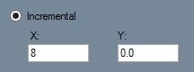
- Incremental: Select the "Incremental" function, provide X and Y coordinates into the "X:" and "Y:" value fields and select a reference point in the display area. X is the horizontal distance and Y is the vertical distance from the reference point. (Note: A negative (-) X value will place the point to the left of the reference point. A negative (-) Y value will place the point below the reference point.) The point will be highlighted in blue while the reference point is being chosen.
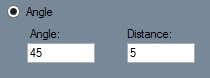
- Angle: Select the "Angle" option under the point tab, enter the distance from the reference point in the "Distance" field and enter an angle in the "Angle" field. If the "Angle" field is set to 0°, the new point will be created directly to the right of the reference point. To place the new point, click on a point to use as a reference point. The point will be highlighted in blue while the reference point is being chosen.
- Absolute: Select the "Absolute" option and enter X and Y coordinates into the "X:" and "Y:" fields and click the "Submit"
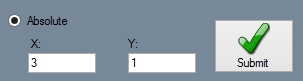
 button to place the point. The reference point will always be (0,0) (or the origin that shows X and Y in the display area).
 - Intersection: Select the "Intersection" option followed by two intersecting lines in order to place a point at the intersection of the two lines.
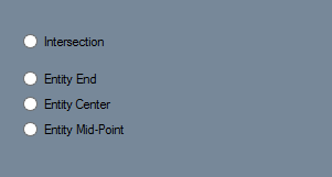
- Entity End: Select the "Entity End" option followed by an object or line in the display area to place an end point of that object. The point will be placed at the end that you click closest to. The point will be highlighted in blue before the object is chosen.
- Entity Center: Select the "Entity Center" option followed by an object or line in the display area to place a center point on that object. The point will be placed directly in the center of the object highlighted. The point will be highlighted in blue and the point will be visible before the object is chosen. (Note: This option is not meant to find the center of self-created objects like flanges, but rather lines, arcs, text, tabs, slots along with holes).
- Entity Mid-Point: Select the "Entity Mid-Point" option followed by an object or line in the display area to place a mid-point on that object. The point will be placed directly in the center of the section of the object highlighted. The point will be highlighted in blue and the point will be visible before the object is chosen. (Note: This option is not meant to find the center of self-created objects like flanges, but rather lines, arcs, text, tabs, slots along with holes).


Line
- Two Points: Select the "Two Points" option, click on a point in the display area and it will turn into a blue circle. Now click on a second point to create a line between the two points. Enable Continuous mode by clicking the "Continuous" checkbox. This will automatically start new lines with the first point set as the end of the last line. To stop drawing lines while in Continuous mode click "Cancel" in the "Activity" section.
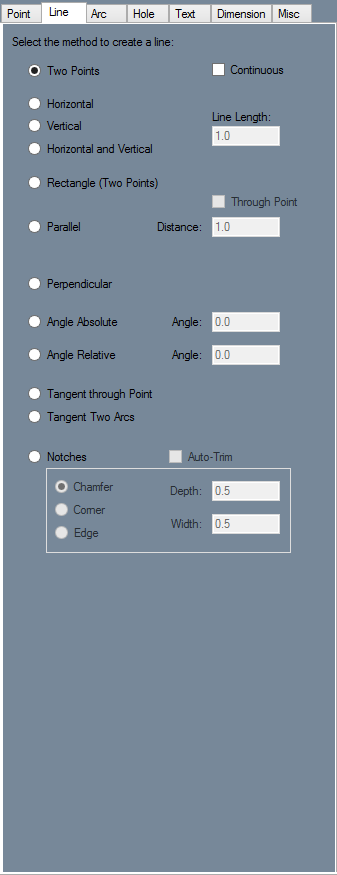
- Horizontal: Select the "Horizontal" option and set the length of the line by entering a value in the "Line Length:" field to create a horizontal line. Place the line by clicking a point in the display area. The mid-point of the line will be centered on the point you select.
- Vertical: Select the "Vertical" option and set the length of the line by entering a value in the "Line Length:" field to create a vertical line. Place the line by clicking a point in the display area. The mid-point of the line will be centered on the point you select.
- Horizontal and Vertical: Select the "Horizontal and Vertical" option to create two intersecting lines of equal length and set the line lengths using the "Line Length:" field. Click on a point to place the lines. Both lines will be placed with the intersection directly over the point you select.
- Rectangle: Select the "Rectangle (Two Points)" option, click a point in the display area and creating a point will cause it to turn into a blue circle. A blue rectangle will be drawn between the selected point and the point nearest the cursor. Move the cursor near the intended second point and make sure the blue rectangle is correct. Click to create the rectangle.
- Parallel: Select "Parallel" so you can either enter the distance between the parallel line and the reference line or use the "Through Point" feature. If a distance is entered and the Through Point checkbox is not selected, click a line to set it as the reference line. After picking the reference line, select which side the parallel line will be placed on by clicking on that side of the reference line. If the Through Point checkbox is selected you must first select a reference line, followed by a point that the parallel line will pass through.
- Perpendicular: Select the "Perpendicular" option to create a line perpendicular to previously established line. Set the length of the perpendicular line using the "Line Length:" field. Then, click a line in the display area to set it as the reference line. The side you click on will determine the direction of the line. Click on any point to place the perpendicular line there.
- Angle Absolute: Select the "Angle Absolute" option to create a line in the display area with a desired angle. First, enter the desired length in the "Line Length:" field and the desired angle in the "Angle:" field. Click on a point to place the Line there.
- Angle Relative: Select the "Angle Relative" option and enter the length of the desired line in the "Line Length:" field and the relative angle in the "Angle:" field. Click on a line to use as a reference line and click on a point to use as a starting point for the new line. The angle of the line will be the sum of the angle of the reference line and the value entered in the Angle field.
- Tangent through Point: Select the "Tangent through Point" option to create a line connected to an arc by clicking near the side of the arc that the line will be drawn to. Click on a point away from the arc to create the line.
- Tangent Two Arcs: Select the "Tangent Two Acrs" option to add a line between two arcs by clicking near the side that the line will be drawn to. Select a second arc to create a line that attaches to the tangent of that arc.
- Notches: Select the "Notches" option and which type of notch you would like to add by clicking either "Chamfer, Corner, or Edge". If adding a Chamfer or Corner, input the desired depth into the "Depth:" field. To add the notch, click on a line and another line that you want the notch to connect to. On the second line, the location that is selected determines which direction the notch faces. Click on the end closest to the direction you want it to face. To add an Edge, you need to input both the Depth and Width. This will create a rectangle with the depth and width that you selected which can be added to the edge of a line. The edge will be added to the closest line and will be placed on the nearest end. An edge can be added to either side of the end of a line by clicking on that side. Check the Auto-Trim box to automatically cut off any part of a line that extends past a notch.

Arc
- Fillet: Select the "Fillet" option and input the desired radius of the filleted arc into the "Radius:" field. Click on the first line, which will turn blue. A blue arc will come off the first line and connect with whatever line is nearest to the cursor. Change the direction of the fillet by moving the cursor to the other side of the first line. Click to place the fillet. If the "Auto-Trim" checkbox is checked, any part of either line that extends past the fillet will be cut off.
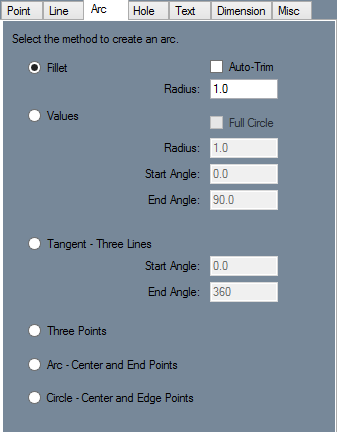
- Values: Select the "Values" option and input the "Radius:, Start Angle:, and End Angle:" of the arc into their respective fields. Click on a point to place the arc with its center directly over that point. Check the "Full Circle" checkbox to automatically set the start angle at "0" and the end angle at "360", creating a full circle.
- Tangent - Three Lines: Select the "Tangent - Three Lines" option and set the start and end angle of the arc using the "Start Angle:" and "End Angle:" fields. Click on three lines within the part, in any order, to create an arc that uses those three lines as tangent lines.
- Three Points: Select the "Three Points" option and pick three points that lie within the desired arc. The first and third points will be end-points. The second point will be on the arc and will define the radius of the arc. If the first and third points are the same point, a circle will be drawn between the first and second point.
- Arc - Center and End Points: Select the "Arc - Center and End Points" option and click on the point that will lie in the center of the intended arc. Click on another point to create the first end point. A blue arc will be drawn from the first end point to the point on the arc closest to the cursor. Move the cursor until the second end point is in the desired location and click to place the arc.
- Circle - Center and Edge Points: Select the "Circle - Center and Edge Points" option and click on a point to set it as the center point. A blue circle will be drawn with a radius equal to the distance to the point nearest to the cursor. Move the cursor to the desired point and click to place the circle.

Hole
- Hole Shape
- Round: Select Round, enter a diameter in the Diameter field, and click on a flange to place a round hole at that point.
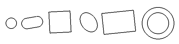
- Oval: Select Oval, enter a width and length in the Width and Length field, and enter an angle for the hole in the Angle field. Click on a PickPoint or endpoint to place an oval hole at that point.
- Square: Select Square, enter a width in the width field, and enter an angle for the hole in the Angle field. If you want to automatically round the corners of the square, you can enter a value in the Corner Radius field. Entering 0 in the Corner Radius field will result in square corners. Click on a PickPoint or endpoint to place an oval hole at that point.
- Ellipse: Select Ellipse and click on the Length button. A window will appear with a diagram of a cylinder going through a plate. You must enter the width and angle of this cylinder in the Diameter of Cylinder and Angle of Cylinder fields. The length of the hole will be calculated automatically. Click the Copy button, close the window, and paste the value into the Length field by clicking in the field and hitting the Control key and the "V" key at the same time. Enter the same width and angle that you used before and click on a point to place an elliptical hole at that location.
- Rectangle: Select Rectangle and enter a width and height in the Width and Height fields. Enter an angle in the Angle field and click on a point to place a rectangular hole at that location.
- Dimple: A dimple is a round hole that is slightly raised, so that the plate around the edges of the hole slope up towards the hole. The Inner Diameter is the section that will actually be cut out of the plate. The Outer Diameter is the area of plate surrounding the hole that slants up towards the hole. Enter an inner and outer diameter and a height in the respective fields. Select Up or Down in order to set whether the dimple is raised or pressed into the plate. Click on a point to place a dimple at that location.
- Hole Patterns
- Single: To place a single hole at the location that you click, select Single.
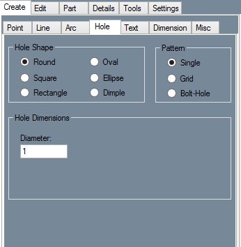
- Grid: To place a grid of holes, select grid. You can place the grid at an angle by entering a value in the Angle field. Enter the number of rows and columns in the grid in the Number of Rows and Number of Columns fields. Enter the spacing between each row in the Row Spacing field and enter the spacing between each column in the Column Spacing field.
- Bolt-Hole: To create a series of holes along an arc, select Bolt-Hole. Enter the radius of the arc in the Radius field. Enter the angle where the series of holes will start in the Start Angle field. To rotate holes as they are placed check the Holes rotate with sweep checkbox. Enter the angular distance between each hole in the Spacing Angle field. Enter the number of holes that you want to place in the Number of Holes field. Click on a point to place the center of the arc at that location.


Text
- Creating Text
- Normal: Click the "New Text" button and type the text that you want in the "Text Properties" text field. Select a font using the "Font Family:" drop down menu and enter a size factor in the "Font Size:" value field. Enter the angle of the intended text in the "Text Angle:" field. Use the "Alignment:" drop down menu to set the text alignment and use the "Line Spacing:" drop down menu to set the spacing between lines of text.
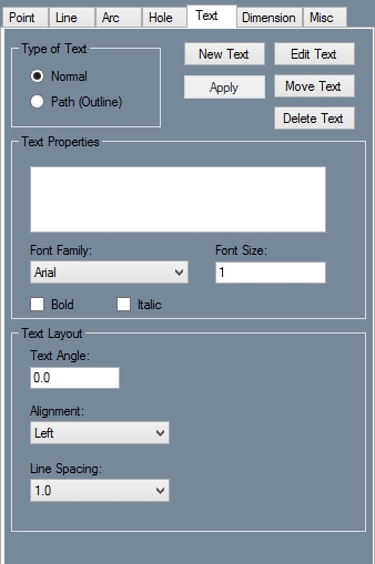
- Path (Outline): When using Path (Outline) to create text, any text you place will be constructed out of lines and arcs which can be used as if they were user placed lines and arcs. The Text Properties area is the same as if you were creating normal text, however the Text Layout area is different. In the Text Angle field enter an angle for the text to be placed at. Enter the spacing between each letter in the Letter Spacing field. To Stretch the string of text horizontally, enter an amount to stretch by in the Horizontal Stretch field. Use the Style drop down menu to choose whether the text is straight or curved. If it is curved up or down, you can enter the radius of the arc that the text is curved around in the Arc Radius field. Use the Precision drop down menu to select the level of detail that the text is drawn with. If you want to create curved but keep each individual letter upright, check the Static Letter Angles checkbox.
- Editing Text
- Edit: To edit an existing string of text, click on the Edit button and click on a previously placed piece of text. Make any changes to the Text Properties and Text Layout areas and click the Apply button.
- Move: To move text, click the move button and click on a string of text. Click on a point to place the text at that location.
- Delete: To delete text, click on the Delete button and click on a string of text.

Dimension
- Create
- Horizontal: Click the Horizontal button and click two points in the display window. A Dimension, along with dimension and extension lines, will appear and move with the cursor. Move the Dimension to the desired location using the cursor and click to place it.
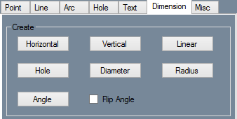
- Vertical: Click the Vertical button and click two points in the display window. A Dimension, along with dimension and extension lines, will appear and move with the cursor. Move the Dimension to the desired location using the cursor and click to place it.
- Linear: Click the Linear button and click two points in the display window. A Dimension, along with dimension and extension lines, will appear and move with the cursor. Move the Dimension to the desired location using the cursor and click to place it.
- Hole: Click the Hole button and click on a hole. The radius of the hole, along with an abbreviated version of the name of its shape, will be drawn and bound to the cursor. Move the cursor until the dimension is in the desired location and click to place it.
- Diameter: Click on the Diameter button. Click on a circle in the display window. A dimension and dimension line will appear in the circle and be bound to the cursor. If the cursor is moved out of the circle an extension line will be drawn in between the circle and the dimension. Move the cursor to reposition the dimension and click to place it.
- Radius: Click the Radius button and click an arc. The radius of the arc, along with a dimension, will be drawn and bound to the cursor. Move the cursor until the dimension is in the desired location and click to place it.
- Angle: Click the Angle button. Click the outside point of the first line. See the picture to the right for an example of outside and inside points. Your points can be endpoints of a line or individual points. Click the inside point of the first line. Now click the outside and inside points of the second line. The dimension, as well as a dimension arc and two extension lines, will be bound to the cursor. Move the cursor until the dimension is in the desired location and click to place it. To measure the reverse of the angle, click the "Flip Angle" checkbox.
- Edit
- Move: Click on the Move button and click on a dimension. The dimension will now move with the mouse and can be repositioned. Click to place the dimension.
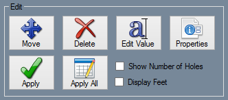
- Delete: Click on the Delete button and click on a dimension to delete it.
- Edit Value: Click on Edit Value and click on a dimension. A window will pop up and ask for a new display value for the dimension. Enter a value and click on the OK button.
- Properties: Click on the "Properties" button and click on a dimension. Make any necessary changes to the settings by clicking in the value field. Standoff, Offset, Text Size, Arrow Width, and Arrow Height can all be changed by typing a new value to replace the existing value. Arrow Type, Distance Tolerance, and Angle Tolerance can be changed by using the drop down menus that appear when their value boxes are clicked. Dim Color, Ext Color, and Text Color can be changed by clicking on their value boxes and selecting the desired color in the color window that appears. To update the dimension with the new settings click on the "Apply:" button.
- Apply: Click on the "Properties:" button and click on a dimension. Make all necessary changes to the dimensions settings. Click Apply to apply the settings to the dimension.
- Apply All: Make any necessary changes to the settings and click on the Apply All button. All dimensions will be updated with these settings.
- Show Number of Holes: Click on this checkbox to display the number of similar holes when creating hole dimensions.
- Display Feet: Click on this checkbox to display feet and inches rather than exclusively inches.
- Setting
- Standoff: Click on the box next to Standoff in the value field and enter a new value to replace the existing one. Use the "Properties:" and "Apply:" buttons to update a single dimension with the new value, or use "Apply All:" to update all dimensions.
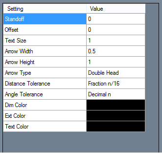
- Offset: Click on the box next to Offset in the value field and enter a new value to replace the existing one. Use the "Properties:" and "Apply:" buttons to update a single dimension with the new value, or use "Apply All:" to update all dimensions.
- Text Size: Click on the box next to Text Size in the value field and enter a new value to replace the existing one. Use the "Properties:" and "Apply:" buttons to update a single dimension with the new value, or use "Apply to All:" to update all dimensions.
- Arrow Width: Click on the box next to Arrow Width in the value field and enter a new value to replace the existing one. Use the "Properties:" and "Apply:" buttons to update a single dimension with the new value, or use "Apply All:" to update all dimensions.
- Arrow Height: Click on the box next to Arrow Height in the value field and enter a new value to replace the existing one. Use the "Properties:" and "Apply:" buttons to update a single dimension with the new value, or use "Apply All:" to update all dimensions.
- Arrow Type: Click on the box next to Arrow Type in the value field and select an option from the drop down menu. Use the "Properties:" and "Apply:" buttons to update a single dimension with the new value, or use "Apply All:" to update all dimensions.
- Distance Tolerance: Click on the box next to Distance Tolerance in the value field and select an option from the drop down menu. Use the "Properties:" and "Apply:" buttons to update a single dimension with the new value, or use "Apply All:" to update all dimensions.
- Angle Tolerance: Click on the box next to Angle Tolerance in the value field and select an option from the drop down menu. Use the "Properties:" and "Apply:" buttons to update a single dimension with the new value, or use "Apply All:" to update all dimensions.
- Dim Color: Click on the box next to Dim Color in the value field. A window will appear where a new color can be chosen. Click on a color and click "OK:". To learn how to define custom colors see the Color page. Use the "Properties:" and "Apply:" buttons to update a single dimension with the new value, or use "Apply All:" to update all dimensions.
- Ext Color: Click on the box next to Ext Color in the value field. A window will appear where a new color can be chosen. Click on a color and click "OK:". To learn how to define custom colors see the Color page. Use the "Properties:" and "Apply:" buttons to update a single dimension with the new value, or use "Apply All:" to update all dimensions.
- Text Color: Click on the box next to Text Color in the value field. A window will appear where a new color can be chosen. Click on a color and click "OK:". To learn how to define custom colors see the Color page. Use the "Properties:" and "Apply:" buttons to update a single dimension with the new value, or use "Apply All:" to update all dimensions.


Misc
- PickPoint
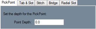
- Point Depth: Enter a depth in the "Point Depth:" field. The Point Depth is the distance on the Z axis from the plate. Click a point to place the PickPoint at the X and Y coordinates of that point. This function is primarily used to help users send their part to the Assembly interface. (Users need 3 directional points of reference in order to transfer their part to Assembly.)

- Type: In the Type area, select either the "Tab:", "Internal Slot:", or "External Slot:" feature to create it along the length of the plate.
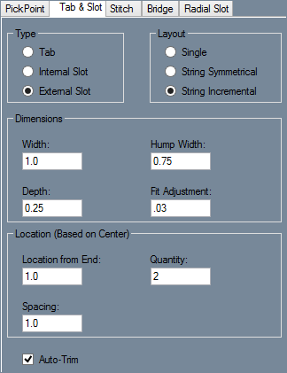
- Layout: In the Layout area, select "Single:" to create a single tab or slot, "String Symmetrical:" to create an evenly spaced series of tabs or slots along a line, or "String Incremental:" to place a series of tabs or slots starting at one end of a line and spaced incrementally by a user selected amount.
- Dimensions: Enter the width of the tabs or slots in the "Width:" value field and enter their depth in the "Depth:" field. Enter the amount that tabs will be undersized and slots that will be over sized in the "Fit Adjustment:" field.
- If you are creating an external slot, enter the width of the humps used to create the slots in the "Hump Width:" field.

- If you are using String Symmetrical or String Incremental, enter the number of tabs or slots you want to create in the "Quantity:" field.
- If you are using String Incremental, enter the spacing between each tab or slot in the "Spacing:" field.
- Use the "Auto-Trim:" checkbox to toggle automatic trimming when creating tabs and slots.
- Center of Current Bend Select "Center of Current Bend:" and make sure to select a bend as the current flange. The Dimensions and Layout values must be completed before placing the stitch(es).
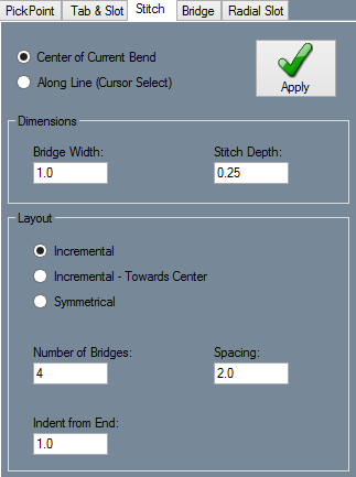
- Along Line (Cursor Select): With the "Along Line (Cursor Select):" option selected, users will see a blue outline of the stitch(es) in the display area before they are placed. Under this function, the stitch(es) will follow along a line or edge of the plate and do not require users to select a defined bend as the current flange. The stitch(es) can be placed anywhere. The Dimensions and Layout values must be completed before placing the stitch(es).
- Dimensions: Enter the width of the bridge(s) in the "Bridge Width:" field and the depth of each stitch in the "Stitch Depth:" field.
- Layout:
- Incremental: If "Incremental:" is selected, enter the number of bridges and spacing between each bridge in the "Number of Bridges:" and "Spacing:" fields. Enter the distance from the edge of the plate to the first stitch in the "Indent from End:" field. (Note) This applies an indent to both edges surrounding the stitche(s).
- Incremental - Towards Center: "Incremental - Towards Center:" works exactly like Incremental, except that the stitches will start at each end and move towards the center.
- Symmetrical: If you are using "Symmetrical:", the stitches will be evenly spaced along the bend. Enter the number of bridges in the Number of Bridges field. Enter the distance between the edge of the plate and the first stitch in the Indent from End field.

- Two-Point Select If the "Two Point Select:" checkbox is checked, enter a width in the "Width:" field. Click the start and end points of the bridge in the display area to create it.
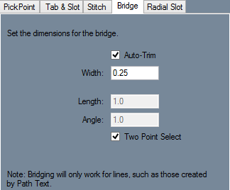
- Auto-Trim To turn off automatic trimming, uncheck the "Auto-Trim:" checkbox. To manually enter the distance and angle of the end point of the bridge, uncheck the "Two Point Select:" checkbox and enter the values in the "Length:" and "Angle:" value fields. Click a point to set it as the start point. Bridges can be made through any line, including lines from path text.

- Radius: Enter the radius of the arc in the Radius field.
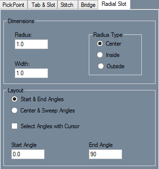
- Radius Type: Select whether the radius is being measured from the center, inside, or outside in the Radius Type area.
- Width: Enter the width of the slot in the Width field. To determine the length of the slot, select either Start & End Angles or Center & Sweep Angles from the Layout area.
- Start & End Angles: Enter a start and end angle for the radial slot in the "Start Angle:" and "End Angle:" fields. Click a point to place the center of the arc at that location.
- Center & Sweep Angles: Enter the angle that will be used as the center of the radial slot in the "Center Angle:" field. Enter the total angular length of the slot in the "Sweep Angle:" field. If Select Angles with Cursor is checked, click a point to set it as the center of the arc. Click another point to set it as the center of the slot. Move the cursor until the slot looks correct and click to place the radial slot.
- Select Angles with Cursor Check the "Select Angles with Cursor:" checkbox and manually select the center and end points of the arc. To do so, check the Select Angles with Cursor checkbox, click a point to set it as the center of the arc, click a point to set it as the beginning of the arc, and move the cursor until the slot is drawn correctly. Click to place the slot.

Edit
Delete
- Selection:
- Selection: Choose the most efficient way to delete entities with modes of "Selection:". Items will be deleted upon selection and after the user has selected the "Complete:" button in the "Activity:" section.
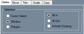
- Cursor Select: Deleting entities with the "Cursor Select:" option is the simplest. Just click on the entity or entities in the display area and select the "Complete:" button in the "Activity:" section to delete them.
- Window: Deleting entities with the "Window:" option is a two-click process. Simply click once to start creating the window and click again when you have enveloped the entity or entities you are trying to delete ("All In" Default). Selecting the "All Out:" option will make it so everything outside the window will be deleted after selecting the "Complete:" button in the "Activity:" section. When the "Include Crossing:" checkbox is checked, every line or entity that touches the window will be included in the deletion process.
- Polygon: When the "Polygon:" option is selected, the user will be able to envelop multiple entities clicking as many times as necessary with the continuous line feature. The entities will be deleted once a previously made line is crossed ("All In" Default). Selecting the "All Out:" option will make it so everything outside the polygon will be deleted after crossing a previously made line and selecting the "Complete:" button in the "Activity:" section. When the "Include Crossing:" checkbox is checked, every line or entity that touches the window will be included in the deletion process.

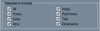
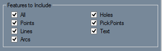
- Features to Include: In the "Features to Include:" section, select which features to include during the deletion process. When selecting multiple entities with a Window or Polygon selection, groups of entities can be selected here to ensure that they will be deleted, or unselected to prevent them from being deleted.

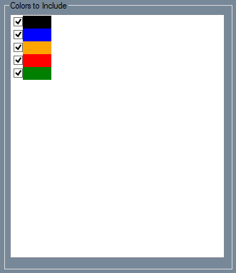
- Colors to Include: is where user's can select which colored parts to include in the deletion process. A color can be selected here to ensure parts of that color will be deleted, or unselected in order to prevent all entities of that color from being deleted.

Move
- Selection:
- Cursor Select: With the "Cursor Select:" option selected, the user can simply click on the entities that are meant to be one at a time. Many functions require the user to click on the Complete button after selecting entities in order to move on to the next step.
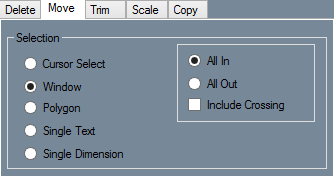
- Window: If "Window:" is selected a box will appear on the right side of the selection area where either "All In:" or "All Out:" may be selected. There is also an "Include Crossing:" checkbox. If All In is selected, the Window tool will allow the drawing of a window that will automatically select all items inside that window. If All Out is selected, the Window tool will automatically select all entities outside of the window. If Include Crossing is checked, items that cross the borders of the window will be included in the selection.
- Polygon: Similar to the Window function, the "Polygon:" option creates a Window using any shape. While using Polygon, make sure the All In/All Out and Include Crossing options are all set correctly. These options work exactly the same as when using Window. Click to create a point. Click again to create another point with a line connecting the two points. Continue clicking to create lines until the desired polygon is drawn. To finish the polygon, make the last line intersect another line to close the shape.
- Single Text: This feature is only present on the Move tab. "Single Text:" allows you to move text by clicking on the anchor point of a string of text to pick it up and clicking again to place it.
- Single Dimension: The "Single Dimension:" option is only present on the Move tab. Click a dimension to pick it up and click again to place it.
- Features to Include:
- Features to Include: In the "Features to Include:" section, select which features to include during the deletion process. When selecting multiple entities with a Window or Polygon selection, groups of entities can be selected here to ensure that they will be deleted, or unselected to prevent them from being deleted.


- Duplicate: Click the "Duplicate:" checkbox and enter the number of copies to be made. Select a Move / Copy Method. Duplicate can be used with any method except for Mirror - Line and Mirror - Two Points. Use the Move method that you select as it is normally used.
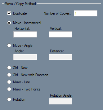
- Move - Incremental: Pick a Selection method from the Selection area. Select "Move - Incremental:" and enter a "Horizontal:" and "Vertical:" distance to move the selection. Negative numbers may be used to move a selection left or down. Make sure the Selection and Move / Copy Method are already selected before clicking in the display window as the move will occur as soon as a selection is made. Select the entity or entities to be moved using the selection method that you chose. The Move will occur instantly upon selection.
- Move - Angle: Choose a Selection method and select "Move - Angle:". In order to specify the direction of the move, an angle must be entered. Keep in mind that 0° is directly to the right. Enter the distance from the original location that the selection should travel. Use the selection method chosen earlier to select an entity or group of entities. The move will occur as soon as the selection is made.
- Old - New: Choose a Selection method and select "Old - New:". Select an entity or multiple entities using the selection method you chose. Click on a point to set that point as the original base point. When a second point is clicked the selection will be moved. The original base point will be directly over the new base point.
- Old - New with Direction: Choose a Selection method and select "Old - New with Direction:". Select the entity or entities using the selection method you chose. Choose an original base point and direction point. Now choose two new points to set as the new base point and direction point. The original base point will be positioned directly over the new base point, and the original direction point will be in line with the base points and the new direction point.
- Mirror - Line: Choose a Selection method and select "Mirror - Line:". Select an entity or group of entities and click on a line. The entities will be mirrored across that line.
- Mirror - Two Points: Choose a Selection method and select "Mirror - Two Points:". Make a selection using the chosen selection method. Choose two points. The entities will be mirrored across the line between the points, regardless of if a line exists there or not. The line between the points will not be drawn.
- Rotation: Choose a selection method and select "Rotation:". Enter an angle in the Rotation Angle field. Select an entity or group of entities using the selection method you chose. Choose a point that the selection will rotate around. As soon as a point is selected, the rotation will be made.

Trim
- Trim Single: With "Trim Single:" selected, click on an entity that intersects another entity. Click on the side of the line that should be kept, rather than the side that is to be trimmed. The side of the entity that you click on will turn blue. Any part of that entity that is not blue will be trimmed off. Move the cursor close to the intersecting entity and make sure the correct section of the entity is blue. Remember that lines continue to infinity even if they are drawn with a finite length, so even if two entities don't touch they could still intersect. Click on the second entity to trim the first entity.
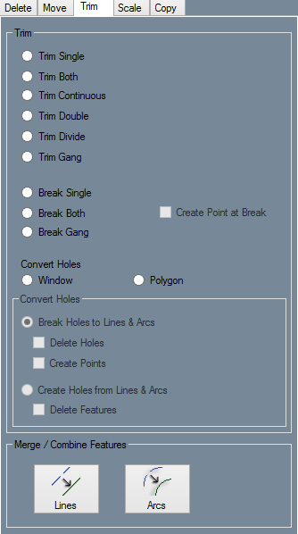
- Trim Both: With "Trim Both:" selected, click on the side of the first entity that should be kept, rather than the side that will be trimmed. The first entity will turn blue. Anything in blue will be kept, while black sections of either entity will be trimmed off. Move the cursor near the second entity and make sure that the correct section of each entity is blue. Click to trim both entities.
- Trim Continuous: With "Trim Continuous:" selected, click on an entity, making sure to click the side that should be kept, rather than the side that will be trimmed off. The entity will turn blue. Move the cursor near the next entity and make sure that every part of the first entity that should be kept is blue. Click to perform the first trim. Click the section of the next entity that should be kept. This will perform another trim. Continue making trims as long as is necessary. Click Cancel in the Activity area at any time to stop trimming.
- Trim Double: With "Trim Double:" selected, click on the entity that will be trimmed. Make sure to click on the section that will be kept, rather than the section that will be trimmed. Click on the two entities that the first entity will be trimmed to.
- Trim Divide: With "Trim Divide:" selected, click on the entity that will be trimmed. Click on two entities that intersect the first entity. The section of the first entity that lies between the second two entities will be removed.
- Trim Gang: With "Trim Gang:" selected, click on the entity that others will be trimmed to. Now click on any intersecting entity to trim it to the first entity. The side of each entity that is clicked on is the side that will be kept.
- Break Single: With "Break Single:" selected, click on an entity and click on an intersecting entity to break the first entity at the intersection point. Check the Create Point at Break box to create a point at the intersection of the two entities.
- Break Both: With "Break Both:" selected, click on two entities in any order. Unlike Break Single, Break Both will break both entities. If the Create Point at Break checkbox is selected, a point will be created at the intersection of the entities.
- Break Gang: With "Break Gang:" selected, click on the entity that will be used to break intersecting entities. Click on the intersecting entities one at a time to break them at the point of intersection with the first entity. If the Create Point at Break box is checked, a point will be created at each break.
- Convert Holes: First, with "Convert Holes:" selected, you must choose whether to convert holes to lines and arcs or convert lines and arcs to holes. To convert holes to lines and arcs, select Break Holes to Lines & Arcs. To delete holes after converting them to lines and arcs, check the Delete Holes checkbox. To create points at the ends of the lines and arcs that are created from converting holes to lines and arcs, check the Create Points checkbox. If Window is selected, draw a window around the holes that you want to convert. If Polygon is selected, draw a polygon around the holes. If you want to create holes based on closed shapes that are made of lines and arcs, select Create Holes from Lines & Arcs. To delete the lines and arcs after converting them to holes, check the Delete Features checkbox. If Window is selected, draw a window around the lines and arcs that you want to convert into a hole. If Polygon is selected, draw a polygon around the features.
- Merge/Combine Features: To merge two lines, click on the "Lines:" button. Click on a line, followed by an second line that the first line will be connected to. To merge two arcs, click on the "Arcs:" button. Click on two arcs to merge them.

Scale
- Selection:
- Selection: Choose the most efficient way to scale entities smaller or larger with modes of "Selection:". Items will be scaled upon selection and after the user has selected the "Complete:" button in the "Activity:" section. They can then place the scaled entity in the display area.
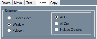
- Cursor Select: Scaling entities with the "Cursor Select:" option is the simplest. Just click on the entity or entities in the display area and select the "Complete:" button in the "Activity:" section to scale them.
- Window: Scaling entities with the "Window:" option is a two-click process. Simply click once to start creating the window and click again when you have enveloped the entity or entities you are trying to resize ("All In" Default). Selecting the "All Out:" option will make it so everything outside the window will be resized after selecting the "Complete:" button in the "Activity:" section. When the "Include Crossing:" checkbox is checked, every line or entity that touches the window will be included in the scaling process.
- Polygon: When the "Polygon:" option is selected, the user will be able to envelop multiple entities clicking as many times as necessary with the continuous line feature. The entities will be scaled once a previously made line is crossed ("All In" Default). Selecting the "All Out:" option will make it so everything outside the polygon will be resized after crossing a previously made line and selecting the "Complete:" button in the "Activity:" section. When the "Include Crossing:" checkbox is checked, every line or entity that touches the window will be included in the scaling process.

- Features to Include: In the "Features to Include:" section, select which features to include during the deletion process. When selecting multiple entities with a Window or Polygon selection, groups of entities can be selected here to ensure that they will be scaled, or unselected to prevent them from being scaled.


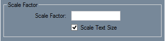
- Scale Factor: Enter a value to multiply the size of selected entities by that factor. To scale items down, use decimals. For example, to half the size of an entity enter 0.5. Negative numbers cannot be used in the Scale Factor field. If the Scale Text Size box is checked, text will be included in the scaling.

- Colors to Include: is where user's can select which colored parts to include in the resizing process. A color can be selected here to ensure parts of that color will be scaled, or unselected in order to prevent all entities of that color from being scaled.
Copy
- Copy:
- Selection: Choose the most efficient way to copy entities smaller or larger with modes of "Selection:". Items will be copied upon selection and after the user has selected the "Complete:" button in the "Activity:" section. They can then paste the copied entity in the display area using the "Paste:" button that appears at the top right part of the screen.
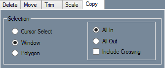
- Cursor Select: copying entities with the "Cursor Select:" option is the simplest. Just click on the entity or entities in the display area and select the "Complete:" button in the "Activity:" section to copy them. They can then paste the copied entity in the display area using the "Paste:" button that appears at the top right part of the screen.
- Window: Copying entities with the "Window:" option is a two-click process. Simply click once to start creating the window and click again when you have enveloped the entity or entities you are trying to copy ("All In" Default). Selecting the "All Out:" option will make it so everything outside the window will be copied after selecting the "Complete:" button in the "Activity:" section. When the "Include Crossing:" checkbox is checked, every line or entity that touches the window will be included in the copying process. They can then paste the copied entity in the display area using the "Paste:" button that appears at the top right part of the screen.
- Polygon: When the "Polygon:" option is selected, the user will be able to envelop multiple entities clicking as many times as necessary with the continuous line feature. The entities will be copied once a previously made line is crossed ("All In" Default). Selecting the "All Out:" option will make it so everything outside the polygon will be copied after crossing a previously made line and selecting the "Complete:" button in the "Activity:" section. When the "Include Crossing:" checkbox is checked, every line or entity that touches the window will be included in the copying process. They can then paste the copied entity in the display area using the "Paste:" button that appears at the top right part of the screen.

- Features to Include: In the "Features to Include:" section, select which features to include during the deletion process. When selecting multiple entities with a Window or Polygon selection, groups of entities can be selected here to ensure that they will be copied, or unselected to prevent them from being copied.
- Old - New: Pick a Selection method and select "Old - New:". Select the entity or entities you wish to copy. Click a point to set it as the base point. This point will be centered on the cursor when pasting the selection. Click on the "Paste:" button, which is located above the display window to the right. Click any point to paste the selection, with the base point centered directly over the point you select.
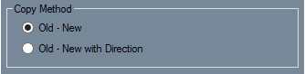
- Old - New with Direction: Choose a Selection method and select "Old - New with Direction:". Use the selection method you chose to select an entity or group of entities. Click a point to set as the base point. This point will be attached to the cursor when pasting the selection. Click a different point to set it as the direction point. The direction point will align with the new base point and direction point. Click on the Paste button, which is located above the display window. Select a new base point and direction point in order to place the copy. For help selecting a base and direction point, see the diagram below.

- Colors to Include: is where user's can select which colored parts to include in the resizing process. A color can be selected here to ensure parts of that color will be scaled, or unselected in order to prevent all entities of that color from being scaled.
Part
- Material: Select a material from the "Material:" drop down menu.
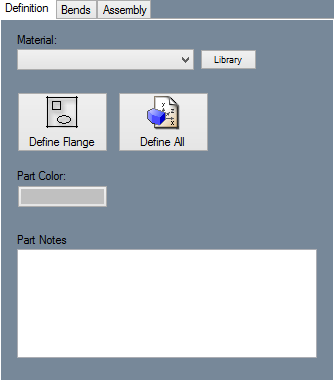
- Library: The "Library:" button can be used to open the Material Library.
- Define Flange: Click the "Define Flange:" button and click on a flange in the display area to define it.
- Define All: If you click the "Define All:" button, the software will attempt to define all flanges with the current settings.
- Part Color: To change the color of a flange, click the "Part Color:" button and use the Color tool to pick a color.
- Part Notes: If desired, you can use the "Part Notes:" field to enter notes about a part.

- New: Click the "New:" button and click a line on a flange in the display area to place the bend there. The bend will be placed with the specifications given in the "Bend Properties:" section.
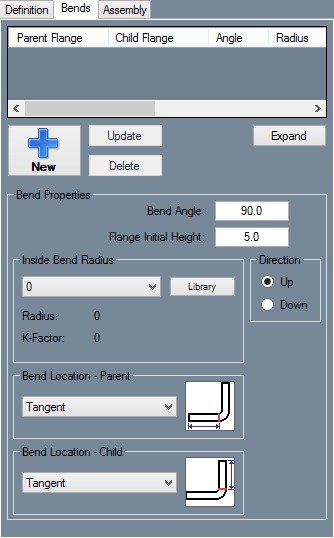
- Update: Use the "Update:" button to update the current information into the Bends List.
- Delete: Select the desired bend and child flange from the Bends List above and select the "Delete:" button to delete the flange.
- Expand: Select the "Expand:" button to show every flange in the Bend List in a new window.
- Bend Angle: Enter the angle of the desired bend in the "Bend Angle:" field.
- Flange Initial Height: Enter the height of the desired bend in the "Flange Initial Height:" field.
- Inside Bend Radius: Use the drop down menu in the "Inside Bend Radius:" area to select a radius for the bend.
- Library: To open the Material Library, click the "Library:" button.
- Direction: Select if the bend should bend up or down in the "Direction:" area.
- Bend Location: Select the "Parent:" and "Child:" bend locations using their respective drop down menus.

Details
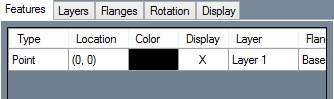
- Features List: In the "Features List:" users can edit a few aspects of each feature. To change a feature's color, click the colored box in the Color column and use the Color tool to select a new color. To toggle the display of the feature, click the box in the Display column. To change a feature's layer, use the drop down menu in the Layer column. When certain types of features are selected, additional options and information may appear for that feature below the Features List.
- Expand: Click the "Expand:" button to see the Features List in a different window.
- Tolerance: Use the "Tolerance:" drop down menu to set the display tolerance of decimals.
- Display Feet and Inches: Click the "Display Feet and Inches:" checkbox to display feet and inches, instead of just inches.

- New: To create a new layer, click the "New:" button.
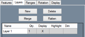
- Delete: To delete a layer, select it from the list of layers and click the "Delete:" button.
- Merge: To merge two layers, make you sure you are on the layer that you want to keep, and select the layer that you want to merge into the current layer. Click the "Merge:" button to merge the two layers.
- Flatten: To merge all layers together into a single layer, click the "Flatten:" button.
- Layers List: The "Layers List:" shows which layers have been created and are in use. From here, users can rename layers by clicking on them and typing a new name in the "Name:" field. Users can select to display which layers are shown by clicking on the field in the "Display:" column. Users can also choose to highlight or dim the a selected layer by clicking on the field in the "Highlight:" or "Dim:" columns.

- Delete: To delete a flange, select it in the list of flanges and click the "Delete:" button.
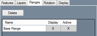
- Display: To toggle the display of a flange, use the checkboxes in the "Display:" column.
- Active: To toggle between active flanges, click on the boxes in the "Active:" column.

- Saved Views: The "Saved Views:" drop down menu shows all the views that have been saved by the user.
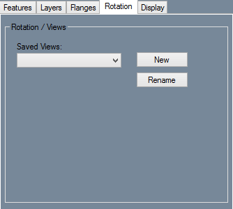
- New: Click the "New:" button and click two points on the part in the display area to create a reference line. That line will be considered a 0° angle. In the "Relative Angle:" field below.(Note: Users must be in "Design Mode:" in order to save views in "Rotation:".)
- Relative Angle: Enter an angle in the "Relative Angle:" field to tilt the display by in relation to the reference line you selected.
- Flip Side: To view the opposing side of the part, check the "Flip Side:" checkbox.
- Rotate 180: To rotate the display 180°, click the "Rotate 180:" checkbox.
- Apply: Click the "Apply:" button to apply the rotation to the display.
- Save: To save the current rotated view, click the "Save:" button, name the view, and click the "OK:" button. You can return to this view by selecting it from the "Saved Views:" drop down menu.
- Rename: First, select a named view from the "Saved Views:" drop down menu and then select the "Rename:" button. A window will appear where users can rename and re-save the view.

- Features to Display: Int the "Features to Display:" section users can show all instances of a specific type of feature by checking the box next to the name of the feature. To hide all instances of a specific type of feature, uncheck the box next to the name of the feature.
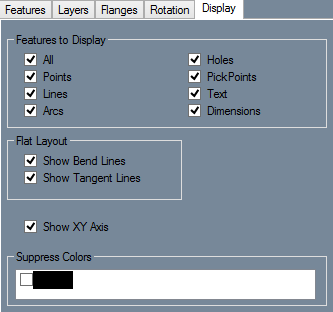
- Flat Layout: In the "Flat Layout:" area you can display bend lines by checking the "Show Bend Lines:" checkbox and display tangent lines by checking the "Show Tangent Lines:" checkbox while using Flat Layout.
- Show XY Axis: Check the "Show XY Axis:" checkbox to display the XY axis (Origin).
- Supress Colors: Hide all features of a certain color by checking the box next to that color in the "Suppress Colors:" area.

Tools
- Create Item: Select the "Create Item:" button and you will be brought to the "Selection Features:" page. From there, choose the method of selection and which Features and Colors to include in the selection process. Once a method is chosen, select an entity or entities from the display area and select the "Complete:" button. Then, to save off the item(s) to the Geometric Library, select the Base Point of the item and name the item. Finally, to get back to the Tools screen, click the "Cancel:" button.
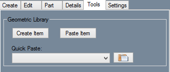
- Paste Item: After an item has been added to the Geometric Library, select the "Paste Item:" button to select the item from the list. In the Library, under the "Options:" section, users can Mirror the part Vertically or Horizontally by checking either checkbox, change the size of the part in the "Scale:" value field, or give the part rotation in the "Rotation:" value field. In the "Properties:" section, users can see the entity's original dimensions in the "Item Bounds:" field and add notes to the "Notes:" section. Select the "Paste:" button on the bottom of the screen to place the item into the display area.
- Quick Paste: If the user has saved predefined parts to the Geometric Library already, they can select the entity from the "Quick Paste:" drop down menu and select the "Paste:" button next to it in order to paste it into the display area. The base point will always be the same as when the user first set it.

- Refresh: Refreshes the Flat Layout. If the Flat Layout is refreshed, any changes that you have made to it using the Tools tab will be lost.
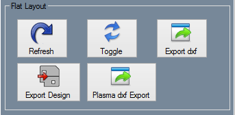
- Toggle: Select the "Toggle:" button to switch between the Design View and the Flat Layout.
- Export dxf: Exports the Flat Layout as a .DXF file and gives all the options to choose the Export Method, What to Export and Unit of Measurement.
- Export Design: Exports the design to a separate Plate file.
- Plasma dxf Export: Exports the design with standard CAD information optimized for plasma cutters.

- Line Type: Select a line type in the overhead Tool Bar and click the Line Type button in the Tools tab. Select a line to change its type.
- Color: Select a color in the Tool Bar. Click the Color button in the Tools tab and use a Selection feature of your choosing. If desired, you may also use the Features to Include function.
- Clean Up: Deletes any duplicate features or zero-length features.
- Flange Intersection: Click on the "Flange Intersection:" button and click on two intersecting flanges. After selecting the intersecting lines of the flanges, the user must trim the excess left over from the intersection and define the part again. See Intersecting Flanges Tutorial for further information.
Settings
- Cursor: The "Cursor:" section simply gives the user to decide whether the look of the cursor is "Default, Small, Small Diagonal or Large".
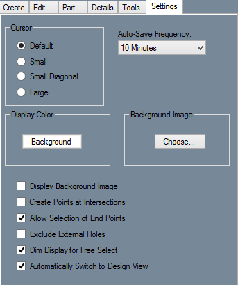
- Auto-Save Frequency: Select the "Auto-Save Frequency:" drop down menu to change how often the software saves your progress.
- Display Color: Click the "Background:" button in the "Display Color:" section to change the background color of the display window.
- Background Image: To display an image in the background of the display window, click the "Choose:..." button and find a picture by using the windows file browser. This works with .bmp/bitmap files only.
- Display Background Image: Toggle the display of a background image in the display window by checking the "Display Background Image:" checkbox.
- Create Points at Intersections: Toggle the automatic creation of points at intersections between entities by checking the "Create Points at Intersections:" checkbox.
- Allow Selection of End Points: End points of lines and arcs can be used as points for the placement of other features by checking the "Allow Selection of End Points:" checkbox.
- Exclude External Holes: Holes that are created outside of a flange will be ignored when checking the "Exclude External Holes:" checkbox.
- Dim Display for Free Select: Toggle the dimming of the display window when "Free Select:" mode is active by checking the "Dim Display for Free Select:" checkbox.
- Automatically Switch to Design View: When the "Automatically Switch to Design View:" checkbox is checked, the display will automatic switch to Design View whenever the Design View is necessary for a function.
