Template
Bend-Tech 7x Wiki :: Template
There are about 150 pre-loaded templates available in the software. Parts can be created using these templates and adding custom values for the part measurements.
Selection
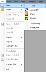
To create a Template part:1.) Go to the File menu, select New, then select Tube. In the Create New menu, click on the Template option.
2.) Click the New Part icon and select the Template option in theCreate New menu.
...OR
3.) Select the Template option from the Task Menu that appears when the software starts up, when all designs are closed, or through the view menu.
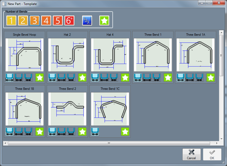
Once Template has been clicked, the New Part-Template menu will be displayed where a part template can be chosen. The templates can be sorted by the number of bends they have using the number buttons at the top of the window.
For example, clicking the 1 button will only show templates with one bend, clicking the two button will only show templates with two bends, and the 6+ button will show templates with six or more bends.
To select a template, click on the template to highlight it in blue. Once a template is highlighted, a dimension option can be chosen. Select either distance from center ![]() , distance from outside
, distance from outside ![]() , or distance from inside
, or distance from inside ![]() by clicking on the appropriate icon. Note: If necessary, this can be changed after the template is selected in the design interface.
by clicking on the appropriate icon. Note: If necessary, this can be changed after the template is selected in the design interface.
Templates can also be saved in the favorites category by clicking the star icon ![]() on the template tile in the selection menu. Favorites will be saved and can be accessed using the Favorites button
on the template tile in the selection menu. Favorites will be saved and can be accessed using the Favorites button ![]() at the top of the menu.
at the top of the menu.
Once the desired template and dimension option are chosen, click the OK button to open a new, blank template design.
Design
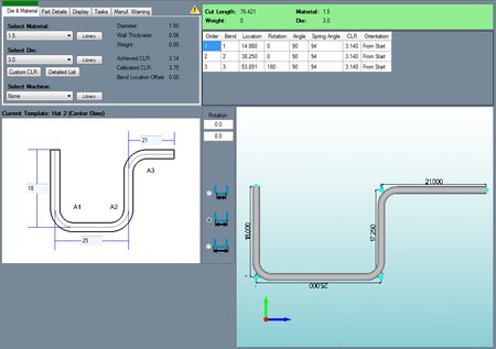
Once the desired template has been properly selected, the template will be opened in the part design interface.
If a default die and material have not been set, a die and material must be chosen before designing the part. If necessary, choose a material, die, and/or machine in the Die and Material tab.
Once they have been chosen, below the tabbed section there will be a 2D display of the chosen part. The name of the template will be shown above this section.
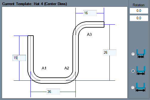
Each dimension requires a value to be entered into its appropriate measurement field.
To add a value to a dimension, enter a numerical value into the field on the blue dimension line. The values that are entered here will be applied to the 3D part display to the right.
To change how the dimensions are measured, click on one of the dimension options to the left of the the design area (Inside, Center, and Outside respectively). These options will determine where the dimensions are placed.
To add rotation to the second and/or any of the consecutive bends, enter rotation values into the rotation fields provided to the right of the design area. The first field will apply rotation to the second bend, the field below that will apply rotation to the third bend, and so on.


