MSP Templates
Bend-Tech 7x Wiki :: MSP Templates
Due to its length, the MSP Templates Guide has a Table of Contents to accommodate the user.
Contents
- 1 Things to Know
- 2 Template Categories
- 3 Template Tabs
- 4 Washers Category
- 5 Beadlocks Category
- 5.1 Beadlock
- 5.2 Beadlock Pattern 1
- 5.3 Beadlock Pattern 2
- 5.4 Beadlock Pattern 3
- 5.5 Beadlock Pattern 4
- 5.6 Beadlock Pattern 5
- 5.7 Beadlock Pattern 6
- 5.8 Beadlock Pattern 7
- 5.9 Beadlock Pattern 8
- 5.10 Brake Dust Cover
- 5.11 Brake Dust Cover Pattern 1
- 5.12 Brake Dust Cover Pattern 2
- 5.13 Brake Dust Cover Pattern 3
- 6 Tabs Category
- 6.1 Universal Tab
- 6.2 Flat Bottom Tab
- 6.3 Link Tab
- 6.4 Link Tab (radius)
- 6.5 Shock Tab
- 6.6 Curved Tab 1
- 6.7 Curved Tab 2
- 6.8 Adjustable Tab
- 6.9 Bolt On Tab
- 6.10 D Ring (flat)
- 6.11 D Ring (radius)
- 6.12 Trick Tab
- 6.13 Zip Tie Tab Centered
- 6.14 Zip Tie Tab
- 6.15 Chassis Tab
- 6.16 Flat Bottom Angled Tab
- 6.17 Link Tab (radius)
- 6.18 D Ring (radius)
Things to Know
The MSP Templates options allow for a variety of Sheet Metal created parts to be designed at the user's specific dimensions. Parts created in the MSP Templates designer can be brought into Sheet Metal and other select interfaces. Parts can also be cut and the wrappers for these cuts can be printed out after being sent to Sheet Metal.
To open a new MSP Template design:
- Select the "MSP Template"
 option from the Task Menu that appears when the software starts up, when all designs are closed, or through the view menu.
- When opening a new template window, it is easier if the user selects the "Maximize"
 button right away. This way, the part chosen by the user will appear in the center of the display area and will not be obstructed by the template's illustration in the upper left hand corner of the screen.
Template Categories
Style of Plate
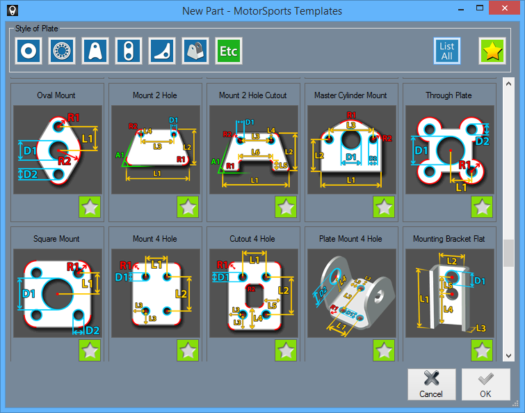
- The "Style of Plate" section shows all of the categories of MSP Templates available.
- Selecting a style from the list will open a new page showing variations of template options for the user to open and adjust to their desired dimensions.
ETC 
- The "'ETC" button will open a new page showing templates that don't easily fall into a discernible category.
List All 
- The "List All" button will show every MSP Template available.
Star 'Favorite' Button 
- The Star, or 'favorite' button will show all the templates that the user has saved to their favorites.
- Clicking the star will change it from white to gold, which indicates a user favorite. All gold starred templates are user favorites.
Template Tabs
- Every template has three tabs. These three tabs will not always have the same buttons and entry fields. The only distinction between the templates is the "Current Template Values" section and what the dimensions there represent.
- (Note) Additional entry fields include "K-Factor:" and "Bending Radius:" and are found in templates with bent sections only.
Material
Define Material:
- From here, users can "Name:" the material being used for the design, specify the "Thickness:", and assign a "Part Color:" to the part displayed to the right.
- Users can also change the length increments by selecting either the "Inches" or "Millimeters" options.
- (For bent templates) "K-Factor:" and "Bend Radius:" value fields are available.
Part Details
- "Notes:" is where the user can make notes about the part's dimensions or specifications.
- "Date:" is where the user can mark when the part was created or when it is set to be manufactured.
- "Revision:" is where the user can update the date when the part specifications were revised.
- "Description:" is where the user can provide a description of the part's specifications.
Ruler
- "Ruler" is where the user can verify dimensions as they appear on all lengths of the part. The ruler angle can be adjusted by clicking on the small icon on the left of the ruler and rotating it. The "Reset"
 button makes the ruler horizontal again. Increments and ruler length can also be easily changed here.
 - (Note) Change between "Millimeters" and "Inches" in the "Material" tab and the ruler will reflect it as well.
Washers Category 
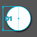
- The first button in the "Style of Plate" section is for "washers and end caps" style projects.
End Cap
Current Template Values:
- The distance labeled "D1" (default 1) is the length of the diameter of the outside edge of the end cap.
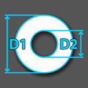
Washer
Current Template Values:
- The distance labeled "D1" (default 1) is the length of the diameter of the outside edge of the washer.
- The distance labeled "D2" (default .5) is the length of the diameter of the inside edge of the washer.
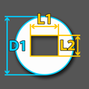
Square Hole Washer
Current Template Values:
- The distance labeled "L1" (default .5) is the length of the horizontal space within the square hole washer.
- The distance labeled "L2" (default .5) is the length of the vertical space within the square hole washer.
- The distance labeled "D1" (default 1) is the length of the diameter of the outside edge of the washer.
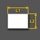
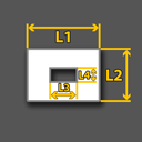
Square End Cap
Current Template Values:
- The distance labeled "L1" (default 2) is the horizontal length of the square end cap.
- The distance labeled "L2" (default 1) is the vertical length of the square end cap.
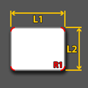
Square End Cap Radius
Current Template Values:
- The distance labeled "L1" (default 2) is the horizontal length of the square end cap.
- The distance labeled "L2" (default 1) is the vertical length of the square end cap.
- The distance labeled "R1" (default .25) is the length of the part's arcs on all four corners.
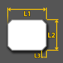
Square End Cap Chamfer
Current Template Values:
- The distance labeled "L1" (default 2) is the horizontal length of the square end cap.
- The distance labeled "L2" (default 1) is the vertical length of the square end cap.
- The distance labeled "L3" (default .25) is the horizontal length of the part's 45 degrees chamfers on all four corners.
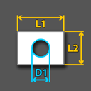
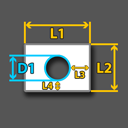
Square Washer
Current Template Values:
- The distance labeled "L1" (default 2) is the horizontal length of the square washer's outer edge.
- The distance labeled "L2" (default 1) is the vertical length of the square washer's outer edge.
- The distance labeled "D1" (default .5) is the length of the diameter of the inside edge of the washer.
Square Washer Square
Current Template Values:
- The distance labeled "L1" (default 2) is the length of the outside horizontal edge of the washer.
- The distance labeled "L2" (default 1) is the length of the outside vertical edge of the washer.
- The distance labeled "L3" (default .5) is the length of the inside vertical edge of the washer.
- The distance labeled "L4" (default .25) is the length of the inside horizontal edge of the washer.
Square Washer
Current Template Values:
- The distance labeled "L1" (default 2) is the length of the outside horizontal edge of the washer.
- The distance labeled "L2" (default 1) is the length of the outside vertical edge of the washer.
- The distance labeled "L3" (default .5) is the length from the inside horizontal edge of the washer to the outside horizontal edge of the washer.
- The distance labeled "L4" (default .25) is the length from the inside vertical edge of the washer to the outside vertical edge of the washer.
- The distance labeled "D1" (default .5) is the length of the diameter of the inside edge of the washer.
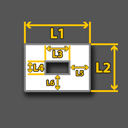
Square Washer Square Hole
Current Template Values:
- The distance labeled "L1" (default 2) is the length of the outside horizontal edge of the washer.
- The distance labeled "L2" (default 1) is the length of the outside vertical edge of the washer.
- The distance labeled "L3" (default .5) is the length of the inside horizontal edge of the washer.
- The distance labeled "L4" (default .25) is the length of the inside vertical edge of the washer.
- The distance labeled "L5" (default .25) is the length from the inside right edge of the washer to the outside right edge of the washer.
- The distance labeled "L6" (default .25) is the length from the lower inside edge of the washer to the lower outside edge of the washer.
Beadlocks Category 
- The second button in the "Style of Plate" section is for "Beadlocks" style projects.
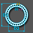
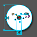
Beadlock
Current Template Values:
- The distance labeled "L1" is the length from the center of the stud hole to the part's edge.
- The distance labeled "D1" is the length of the diameter of the outside edge of the part.
- The distance labeled "D2" is the length of the diameter of the inside edge of the part.
- The distance labeled "D3" is the length of the diameter of the stud holes.
- The value labeled "#" is the number of stud holes the user would like to create circling the part.
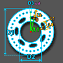
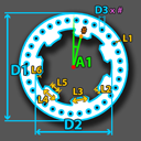
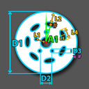
Beadlock Pattern 1
Current Template Values:
- The value labeled "A1" is the angle which offsets the inner pattern design holes and outer stud holes.
- The distance labeled "L1" is the length from the center of the outer stud hole to the part's edge.
- The distance labeled "L2" is the length from the center of the inner design pattern hole to the part's edge.
- The distance labeled "L3" is the height of the inner pattern design hole.
- The distance labeled "L4" is the width of the inner design pattern hole.
- The distance labeled "D1" is the length of the diameter of the outside edge of the part.
- The distance labeled "D2" is the length of the diameter of the inside edge of the part.
- The distance labeled "D3" is the length of the diameter of the outer stud holes.
- The pink "#" is the number of stud holes the user would like to create circling the part on the outside.
- The orange "#" is the number of pattern design holes the user would like to create circling the part on the inside.
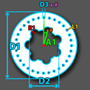
Beadlock Pattern 2
Current Template Values:
- The value labeled "A1" is the angle which offsets the inner pattern design holes and outer stud holes.
- The distance labeled "L1" is the length from the center of the outer stud hole to the part's edge.
- The distance labeled "R1" is the length from the center of the inner hole to the its arc.
- The distance labeled "D1" is the length of the diameter of the outside edge of the part.
- The distance labeled "D2" is the length of the diameter of the inside edge of the part.
- The distance labeled "D3" is the length of the diameter of the outer stud holes.
- The pink "#" is the number of stud holes the user would like to create circling the part on the outside.
- The orange "#" is the number of pattern design holes the user would like to create circling the part on the inside.
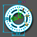
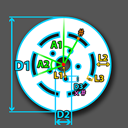
Beadlock Pattern 3
Current Template Values:
- The value labeled "A1" is the angle which offsets the inner pattern design holes and outer stud holes.
- The value labeled "A2" is the angle from the center of the part which determines the width of each section of the inner pattern.
- The distance labeled "L1" is the length from the center of the outer stud hole to the part's edge.
- The distance labeled "L2" is the length from the inner hole's edge to the inner design pattern's edge.
- The distance labeled "L3" is the length from the inner hole's edge to the outer edge of the pattern design hole.
- The distance labeled "D1" is the length of the diameter of the outside edge of the part.
- The distance labeled "D2" is the length of the diameter of the inside edge of the part.
- The distance labeled "D3" is the length of the diameter of the outer stud holes.
- The pink "#" is the number of stud holes the user would like to create circling the part on the outside.
- The orange "#" is the number of pattern design holes the user would like to create circling the part on the inside.
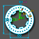
Beadlock Pattern 4
Current Template Values:
- The value labeled "A1" is the angle which offsets the inner pattern design holes and outer stud holes.
- The value labeled "A2" is the angle from the center of the part which determines the width of each section of the inner pattern.
- The distance labeled "L1" is the length from the center of the outer stud hole to the part's edge.
- The distance labeled "L2" is the width of the inner design pattern's edge.
- The distance labeled "L3" is the height of the inner hole's edge.
- The distance labeled "D1" is the length of the diameter of the outside edge of the part.
- The distance labeled "D2" is the length of the diameter of the inside edge of the part.
- The distance labeled "D3" is the length of the diameter of the outer stud holes.
- The pink "#" is the number of stud holes the user would like to create circling the part on the outside.
- The orange "#" is the number of pattern design holes the user would like to create circling the part on the inside.
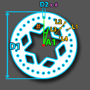
Beadlock Pattern 5
Current Template Values:
- The value labeled "A1" is the angle which offsets the inner pattern design tabs and outer stud holes.
- The distance labeled "L1" is the length from the center of the outer stud hole to the part's edge.
- The distance labeled "L2" is the height of the inner design pattern's edge.
- The distance labeled "L3" is the width of the midpoint on the inner design pattern's edge.
- The distance labeled "L4" is the width of the base point on the inner design pattern's edge.
- The distance labeled "L5" is the width of the endpoint on the inner design pattern's edge.
- The distance labeled "L6" is the height from the base point to the midpoint on the inner design pattern's edge. This value must always be less than L2.
- The distance labeled "D1" is the length of the diameter of the outside edge of the part.
- The distance labeled "D2" is the length of the diameter of the inside edge of the part.
- The distance labeled "D3" is the length of the diameter of the outer stud holes.
- The pink "#" is the number of stud holes the user would like to create circling the part on the outside.
- The orange "#" is the number of pattern design tabs the user would like to create circling the part on the inside.
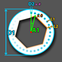
Beadlock Pattern 6
Current Template Values:
- The value labeled "A1" is the angle which offsets the inner polygon point's edge and the outer stud holes.
- The distance labeled "L1" is the length from the center of the outer stud hole to the part's edge.
- The distance labeled "L2" is the length from the inner polygon point's edge to the part's edge.
- The distance labeled "D1" is the length of the diameter of the outside edge of the part.
- The distance labeled "D2" is the length of the diameter of the stud holes.
- The pink "#" is the number of stud holes the user would like to create circling the part on the outside.
- The orange "#" is the number of polygon points the user would like to create circling the part on the inside.
Beadlock Pattern 7
Current Template Values:
- The value labeled "A1" is the angle which offsets the inner polygon point's edge and outer stud holes.
- The distance labeled "L1" is the length from the center of the outer stud hole to the part's edge.
- The distance labeled "L2" is the length from the inner polygon point's edge to the part's edge.
- The distance labeled "L3" is the height of the inner pattern design hole.
- The distance labeled "L4" is the width of the inner design pattern border.
- The distance labeled "D1" is the length of the diameter of the outside edge of the part.
- The distance labeled "D2" is the length of the diameter of the stud holes.
- The pink "#" is the number of stud holes the user would like to create circling the part on the outside.
- The orange "#" is the number of polygon points the user would like to create circling the part on the inside.
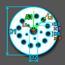
Beadlock Pattern 8
Current Template Values:
- The value labeled "A1" is the angle which offsets the inner pattern design holes and outer stud holes.
- The distance labeled "L1" is the length from the center of the outer stud hole to the part's edge.
- The distance labeled "L2" is the length from the center of the inner design pattern hole to the part's edge.
- The distance labeled "D1" is the length of the diameter of the outside edge of the part.
- The distance labeled "D2" is the length of the diameter of the inside edge of the part.
- The distance labeled "D3" is the length of the diameter of the outer stud holes.
- The distance labeled "D4" is the length of the diameter of the inner design pattern holes.
- The pink "#" is the number of stud holes the user would like to create circling the part on the outside.
- The orange "#" is the number of pattern design holes the user would like to create circling the part on the inside.
Brake Dust Cover
Current Template Values:
- The distance labeled "L1" is the length from the center of the part to the center of any outer stud hole.
- The distance labeled "D1" is the length of the diameter of the outside edge of the part.
- The distance labeled "D2" is the length of the diameter of the inside edge of the part.
- The distance labeled "D3" is the length of the diameter of the outer stud holes.
- The pink "#" is the number of stud holes the user would like to create circling the part on the outside.
Brake Dust Cover Pattern 1
Current Template Values:
- The value labeled "A1" is the angle which offsets the inner pattern design holes and outer stud holes.
- The distance labeled "L1" is the length from the center of the part to the center of any inner stud hole.
- The distance labeled "L2" is the length from the center of the outer pattern design hole to the part's edge.
- The distance labeled "L3" is the height of the outer pattern design hole.
- The distance labeled "L4" is the width of the outer design pattern border.
- The distance labeled "D1" is the length of the diameter of the outside edge of the part.
- The distance labeled "D2" is the length of the diameter of the inside edge of the part.
- The distance labeled "D3" is the length of the diameter of the inner stud holes.
- The pink "#" is the number of stud holes the user would like to create circling the part on the inside.
- The orange "#" is the number of pattern design holes the user would like to create circling the part on the outside.
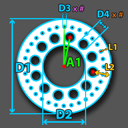
Brake Dust Cover Pattern 2
Current Template Values:
- The value labeled "A1" is the angle which offsets the inner pattern design holes and outer stud holes.
- The distance labeled "L1" is the length from the center of the part to the center of any inner stud hole.
- The distance labeled "L2" is the length from the center of the outer pattern design hole to the part's edge.
- The distance labeled "D1" is the length of the diameter of the outside edge of the part.
- The distance labeled "D2" is the length of the diameter of the inside edge of the part.
- The distance labeled "D3" is the length of the diameter of the inner stud holes.
- The distance labeled "D4" is the length of the diameter of the outer design pattern holes.
- The pink "#" is the number of stud holes the user would like to create circling the part on the inside.
- The orange "#" is the number of pattern design holes the user would like to create circling the part on the outside.
Brake Dust Cover Pattern 3
Current Template Values:
- The value labeled "A1" is the angle which offsets the inner pattern design holes and outer stud holes.
- The value labeled "A2" is the angle which determines the length of the outer design pattern holes.
- The distance labeled "L1" is the length from the center of the part to the center of any inner stud hole.
- The distance labeled "L2" is the length from the center of the outer pattern design hole to the part's edge.
- The distance labeled "L3" is the height of the outer pattern design hole.
- The distance labeled "D1" is the length of the diameter of the outside edge of the part.
- The distance labeled "D2" is the length of the diameter of the inside edge of the part.
- The distance labeled "D3" is the length of the diameter of the inner stud holes.
- The pink "#" is the number of stud holes the user would like to create circling the part on the inside.
- The orange "#" is the number of pattern design holes the user would like to create circling the part on the outside.
Tabs Category 
- The third button in the "Style of Plate" section is for "Tabs and D-Rings" style projects.
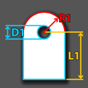
Universal Tab
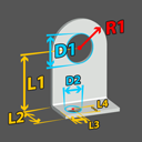
Current Template Values:
- The distance labeled "L1" (default 2) is the length from the center of the hole to the part's bottom edge.
- The distance labeled "R1" (default 1) is the length from the center of the hole to the part's arc.
- The distance labeled "D1" (default .5) is the length of the diameter of the part's hole.
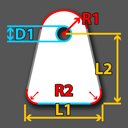
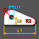
Flat Bottom Tab
Current Template Values:
- The distance labeled "L1" (default 3) is the entire width along the part's bottom edge.
- The distance labeled "L2" (default 2) is the length from the center of the hole to the part's bottom edge.
- The distance labeled "R1" (default 1) is the length from the center of the hole to the part's top arc.
- The distance labeled "R2" (default .1) is the size of the part's bottom arcs.
- The distance labeled "D1" (default .5) is the length of the diameter of the part's hole.
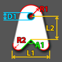
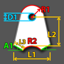
Link Tab
Current Template Values:
- The value labeled "A1" (default 90) is the angle at which the bottom two legs of the part meet.
- The distance labeled "L1" (default 2) is the entire width along the part's bottom edge.
- The distance labeled "L2" (default 1) is the length from the center of the hole to the A1 angle's edge.
- The distance labeled "R1" (default 1) is the length from the center of the hole to the part's top arc.
- The distance labeled "R2" (default .25) is the size of the part's bottom arcs.
- The distance labeled "D1" (default .5) is the length of the diameter of the part's hole.
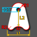
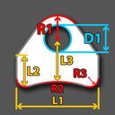
Link Tab (radius)
Current Template Values:
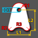
- The distance labeled "L1" (default 3) is the entire width along the part's bottom edge.
- The distance labeled "L2" (default 2) is the length from the center of the hole to the part's bottom arc.
- The distance labeled "R1" (default 1) is the length from the center of the hole to the part's top arc.
- The distance labeled "R2" (default .25) is the size of the part's bottom arcs.
- The distance labeled "R3" (default 2.5) is the size of the part's inner bottom arc.
- The distance labeled "D1" (default .5) is the length of the diameter of the part's hole.
Shock Tab
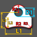
Current Template Values:
- The value labeled "A1" (default 15) is the angle at which the bottom two legs of the part rise from the base.
- The distance labeled "L1" (default 3) is the entire width along the part's bottom edge.
- The distance labeled "L2" (default 2) is the length from the center of the hole to the R2 arc's edge.
- The distance labeled "L3" (default .25) is the length from the edge of the part to the edge of the R2 arc.
- The distance labeled "R1" (default 1) is the length from the center of the hole to the part's top arc.
- The distance labeled "R2" (default 1.5) is the size of the part's inner bottom arc.
- The distance labeled "D1" (default .5) is the length of the diameter of the part's hole.
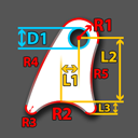
Curved Tab 1
Current Template Values:
- The distance labeled "L1" (default 2) is the horizontal offset length from the center of the hole to the top of the part's R2 arc.
- The distance labeled "L2" (default 2) is the vertical length from the center of the hole to the R2 arc's edge.
- The distance labeled "L3" (default 2) is the vertical length from the bottom edge of the part to the edge of the R2 arc.
- The distance labeled "R1" (default 1) is the length from the center of the hole to the part's top arc.
- The distance labeled "R2" (default 1) is the size of the part's inner bottom arc.
- The distance labeled "R3" (default 1) is the size of the part's bottom arcs.
- The distance labeled "R4" (default 1) is the size of the part's left arc.
- The distance labeled "R5" (default 1) is the size of the part's right arc.
- The distance labeled "D1" (default .5) is the length of the diameter of the part's hole.
Curved Tab 2
Current Template Values:
- The distance labeled "L1" (default .5) is the horizontal length from the center of the hole to the center of R2 arc.
- The distance labeled "L2" (default 2) is the vertical length from the center of the hole to the R2 arc's edge.
- The distance labeled "L3" (default 1) is the vertical length from the bottom right edge of the part to the edge of the R1 arc.
- The distance labeled "R1" (default 1) is the length from the center of the hole to the part's top arc.
- The distance labeled "R2" (default 1) is the size of the part's inner bottom arc.
- The distance labeled "R3" (default .25) is the size of the part's bottom arcs.
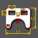
Adjustable Tab
Current Template Values:
- The distance labeled "L1" (default 2) is the horizontal length from the left edge of the part to the right edge of the part.
- The distance labeled "L2" (default 1.5) is the vertical length from the top of the part to the bottom R2 arc's edge.
- The distance labeled "L3" (default .25) is the vertical length from the top edge of the holes to the top of the part.
- The distance labeled "L4" (default .5) is the horizontal length of the holes in the part.
- The distance labeled "L5" (default .375) is the vertical length of the holes in the part.
- The distance labeled "L6" (default .5) is the horizontal distance between the two top holes.
- The distance labeled "R1" (default .75) is the size of the part's center bottom arc.
- The distance labeled "R2" (default .25) is the size of the part's outer bottom arcs.
- The distance labeled "R3" (default .125) is the size of the hole's arcs.
Bolt On Tab
Current Template Values:
- The distance labeled "L1" (default 2) is the length from the center of the top hole to the base of the part.
- The distance labeled "L2" (default .5) is the depth of the base part.
- The distance labeled "L3" (default .25) is the vertical length from the bottom edge of the part to the center of the D2 hole.
- The distance labeled "L4" (default .25) is the horizontal length from the bottom left edge of the part to the center of the D2 hole.
- The distance labeled "R1" (default 1) is the length from the center of the hole to the part's top arc.
- The distance labeled "D1" (default .5) is the length of the diameter of the part's top hole.
- The distance labeled "D2" (default .125) is the length of the diameter of the part's bottom hole.
D Ring (flat)
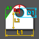
Current Template Values:
- The value labeled "A1" (default 30) is the angle at which the two side edges of the part turn inward near the top.
- The distance labeled "L1" (default 3) is the length of the base of the part.
- The distance labeled "L2" (default 2) is the length from the center of the hole to the base of the part.
- The distance labeled "R1" (default 1) is the length from the center of the hole to the part's arc.
- The distance labeled "D1" (default .5) is the length of the diameter of the part's hole.
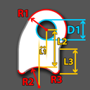
D Ring (radius)
Current Template Values:
- The distance labeled "L1" (default 4) is the length of the base of the part.
- The distance labeled "L2" (default 2) is the length from the angle's cutoff on each side to the base of the part.
- The distance labeled "L3" (default 3) is the vertical length from the center of the hole to the base arc of the part.
- The distance labeled "R1" (default 1) is the length from the center of the hole to the part's top arc.
- The distance labeled "R2" (default 4) is the size of the part's inner bottom arc.
- The distance labeled "R3" (default .25) is the size of the part's bottom arcs.
- The distance labeled "D1" (default .5) is the length of the diameter of the part's hole.
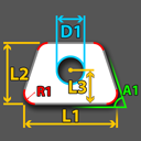
Trick Tab
Current Template Values:
- The value labeled "A1" (default 60) is the angle at which the two side edges of the part turn inward near the top.
- The distance labeled "L1" (default 2) is the length of the base of the part.
- The distance labeled "L2" (default 1) is the length from the angle's cutoff on each side to the base of the part.
- The distance labeled "L3" (default .5) is the vertical length from the center of the hole to the base of the part.
- The distance labeled "R1" (default .25) is the size of the part's arcs.
- The distance labeled "D1" (default .5) is the length of the diameter of the part's hole.
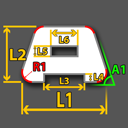
Zip Tie Tab Centered
Current Template Values:
- The value labeled "A1" (default 60) is the angle at which the two side edges of the part turn inward near the top.
- The distance labeled "L1" (default 3) is the length of the base of the part.
- The distance labeled "L2" (default 1.5) is the length from the base of the part to the top of the part.
- The distance labeled "L3" (default .75) is the horizontal length of the gap in the base of the part.
- The distance labeled "L4" (default .25) is the vertical length of the gap in the base of the part.
- The distance labeled "L5" (default .25) is the vertical length of the hole in the part.
- The distance labeled "L6" (default .5) is the horizontal length of the hole in the part.
- The distance labeled "R1" (default .25) is the size of the part's arcs.
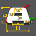
Zip Tie Tab
Current Template Values:
- The value labeled "A1" (default 60) is the angle at which the two side edges of the part turn inward near the top.
- The distance labeled "L1" (default 3) is the length of the base of the part.
- The distance labeled "L2" (default 1.5) is the length from the base of the part to the top of the part.
- The distance labeled "L3" (default .75) is the horizontal length of the gap in the base of the part.
- The distance labeled "L4" (default .25) is the vertical length of the gap in the base of the part.
- The distance labeled "L5" (default .25) is the vertical length of the hole in the part.
- The distance labeled "L6" (default .5) is the horizontal length of the hole in the part.
- The distance labeled "L7" (default .25) is the vertical length from the top of the gap to the lower edge of the hole in the part.
- The distance labeled "R1" (default .25) is the size of the part's arcs.
Chassis Tab
Current Template Values:
- The distance labeled "L1" (default 4) is the length of the base of the part.
- The distance labeled "L2" (default 2) is the length from the center of the hole to the base of the part.
- The distance labeled "R1" (default 1) is the length from the center of the hole to the part's top arc.
- The distance labeled "R2" (default .25) is the size of the part's bottom right arc.
- The distance labeled "D1" (default .5) is the length of the diameter of the part's hole.
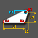
Flat Bottom Angled Tab
Current Template Values:
- The distance labeled "L1" (default 4) is the length of the base of the part.
- The distance labeled "L2" (default 1) is the horizontal length from the top right edge of the part to the bottom right "R2" arc of the part.
- The distance labeled "L3" (default 2) is the length from the center of the hole to the base of the part.
- The distance labeled "R1" (default .5) is the length from the center of the hole to the part's top arc.
- The distance labeled "R2" (default .25) is the size of the part's bottom arcs.
- The distance labeled "D1" (default .5) is the length of the diameter of the part's hole.
Link Tab (radius)
Current Template Values:
- The distance labeled "L1" (default 3) is the entire width along the part's bottom edge.
- The distance labeled "L2" (default 2) is the vertical length from the center of the hole to the part's bottom arcs.
- The distance labeled "R1" (default 1) is the length from the center of the hole to the part's top arc.
- The distance labeled "R2" (default .25) is the size of the part's bottom arcs.
- The distance labeled "R3" (default 2.5) is the size of the part's inner bottom arc.
- The distance labeled "D1" (default .5) is the length of the diameter of the part's hole.
D Ring (radius)
Current Template Values:
- The value labeled "A1" (default 30) is the angle at which the two side edges of the part turn inward near the top.
- The distance labeled "L1" (default 4) is the length of the base of the part.
- The distance labeled "L2" (default 2) is the length from the angle's cutoff on each side to the base of the part.
- The distance labeled "L3" (default 3) is the vertical length from the center of the hole to the base of the part.
- The distance labeled "R1" (default 1) is the length from the center of the hole to the part's top arc.
- The distance labeled "R2" (default 4) is the size of the part's inner bottom arc.
- The distance labeled "R3" (default .25) is the size of the part's bottom arcs.
- The distance labeled "D1" (default .5) is the length of the diameter of the part's hole.
Due to the length of the MSP Templates section, template information continues on Motor Sports Templates II
