Nesting
Bend-Tech 7x Wiki :: Nesting
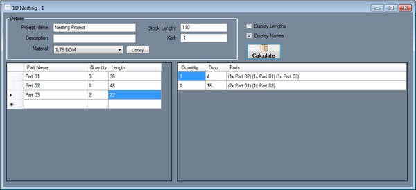
- Nesting helps determine how many parts of different lengths can be created from a single length of tube. The length of the main
tube is given as well as the lengths of each individual part and how many are needed. After these values are supplied, a list of the
parts that can be made out of each length of the main tube is generated. The amount of leftover tube is supplied as well.
Details
- Project Name: A name for the current nesting project can be supplied here.
- Description: A description of the project can be added here.
- Material: The material of the project is given in the Material field. This is the material of the main length of tube and all of the parts. Click the Library option to open up the Tube/Pipe Library.
- Stock Length: The stock length of the main tube is given in the Stock Length field.
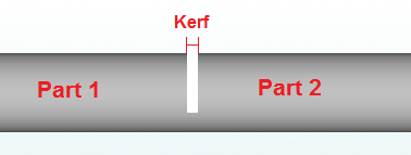
- Kerf: The cut/saw width is given in the Kerf field. This is the amount of material that will be removed when making a single cut. See image below.
Add Part
Each individual part is added to the chart on the left. There is a column for the part name, number of parts needed, and the length of the part. Parts can be added a couple different ways.
1.) By transferring a part over to a new or existing nesting project directly from a designer. To do so, click the Transfer menu ![]() and select one of the nesting options.
and select one of the nesting options.
2.) By manually typing in a part name, number of parts needed, and the total length of the part. To do this, click in the name field in next empty row. Type in the name of the part. Click the tab key, or click in the next column to type in how many of this part is needed. Click the tab key, or click in the next column and enter the length of this part. Once these three values are supplied, a part has been successfully added to the nesting project.
Calculate Results
Once all of the parts are correctly added to the left chart, and the total length of the main tube and the cut length are entered, the nesting chart can be created. Click the Calculate button ![]() to create the nesting chart.
to create the nesting chart.
Each row will represent the parts that can be made from the number of main tube(s) specified in the first column. This chart will consist of three columns. The first represents the quantity of main tube lengths required to create the parts in that row. The second represents the amount of material that will be leftover after running the parts that are listed in the third column. The third lists all the parts that can be made from the main tube(s).
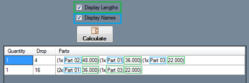
The third column can be customized using the Display Lengths and Display Names check boxes directly above the nesting chart. These control what information is included with each part or set of parts. At least one should be checked for information to be displayed in the chart. See image below for an example.
To print out the nesting charts, click the Print icon ![]() or use the File -> Print option. This will print out the nesting project details along with the parts chart and the results chart.
or use the File -> Print option. This will print out the nesting project details along with the parts chart and the results chart.


