Difference between revisions of "Assembly"
| Line 1: | Line 1: | ||
| − | '''[[Main Page|Bend-Tech 7x Wiki]] :: Assembly''' [[File:assembly_1.png|right| | + | '''[[Main Page|Bend-Tech 7x Wiki]] :: Assembly''' [[File:assembly_1.png|right|500px]] |
__NOTOC__ | __NOTOC__ | ||
| Line 5: | Line 5: | ||
| + | '''To open a new assembly design:''' | ||
| + | 1.) Go to the '''File''' menu, select '''New Assembly'''. | ||
| + | 2.) Click the '''New Assembly''' icon at the top of the window. | ||
| + | '''...OR''' | ||
| + | |||
| + | 3.) Select the '''Assembly''' option from the [[View#Task Menu|Task Menu]] that appears when the software starts up, when all designs are closed, or through the view menu. | ||
| + | |||
| + | |||
| + | |||
| + | |||
| + | |||
| + | |||
| + | When a new assembly window is open, there will be a '''menu area''' located above the tabbed section and display frame. | ||
| + | |||
| + | [[File:assembly_2.png]] | ||
| + | |||
| + | |||
| + | <h4>Material</h4> | ||
| + | In the material menu, the material for the parts in the assembly can be selected. '''To select a material''', click the drop down menu and choose a material from the list. This material can be changed for each individual part later, this is just the material that is initially applied to new parts. Tube/pipe materials are defined in the [[Tube/Pipe Library]]. | ||
| + | |||
| + | |||
| + | <h4>Die</h4> | ||
| + | In the die menu, the die used to bend the parts in the assembly can be selected. '''To select a die''', click the drop down menu and choose a die from the list. This can be changed for each individual part later, this is just the die that is initially applied to new parts. Dies are defined in the [[Die Library]]. | ||
| + | |||
| + | |||
| + | <h4>Straight</h4> | ||
| + | |||
| + | <h4>Bent</h4> | ||
| + | |||
| + | <h4>Delete</h4> | ||
| + | |||
| + | <h4>Entities</h4> | ||
| + | |||
| + | <h4>Bend Mode</h4> | ||
| + | |||
| + | <h4>Settings</h4> | ||
Revision as of 14:24, 5 June 2014
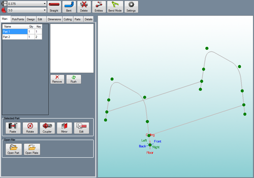
The assembly interface allows a group of different bent and straight parts to be assembled together. Parts created in the single part designers (XYZ, Custom 3D, Sketch 2D, etc.) can be brought into assembly and parts within assembly can be transferred to single part designers. Parts can also be cut and the wrappers for these cuts can be printed out here.
To open a new assembly design:
1.) Go to the File menu, select New Assembly.
2.) Click the New Assembly icon at the top of the window.
...OR
3.) Select the Assembly option from the Task Menu that appears when the software starts up, when all designs are closed, or through the view menu.
When a new assembly window is open, there will be a menu area located above the tabbed section and display frame.
Material
In the material menu, the material for the parts in the assembly can be selected. To select a material, click the drop down menu and choose a material from the list. This material can be changed for each individual part later, this is just the material that is initially applied to new parts. Tube/pipe materials are defined in the Tube/Pipe Library.
Die
In the die menu, the die used to bend the parts in the assembly can be selected. To select a die, click the drop down menu and choose a die from the list. This can be changed for each individual part later, this is just the die that is initially applied to new parts. Dies are defined in the Die Library.
Straight
Bent
Delete
Entities
Bend Mode
Settings

