Difference between revisions of "Custom Part"
| Line 29: | Line 29: | ||
| − | *The '''number of bends''' in the part can be chosen from the 'Number of Bends | + | *The '''number of bends''' in the part can be chosen from the "'''Number of Bends'''" drop down menu. Up to 50 bends can be added to a part. |
Latest revision as of 08:03, 30 September 2014
Bend-Tech 7x Wiki :: Custom Part
- Custom parts can be created by supplying length, rotation, and angle values.
Selection
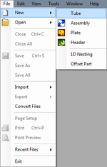
To create a Custom Part:1.) Go to the File menu, select New, then select Tube. In the Create New menu, click on the Custom Part option.
2.) Click the New Part icon and select the Custom Part option in theCreate New menu.
...OR
3.) Select the Custom Part option from the Task Menu that appears when the software starts up, when all designs are closed, or through the view menu.
Design
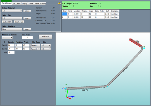
- Once Custom Part has been selected, a new custom part window will open. If a default die and material have not been set, a die, material, and/or machine must be chosen before designing the part. If necessary, choose a material, die, and/or machine in the Die and Material tab. Once a die and material have been chosen, the custom part design section will be available to use.
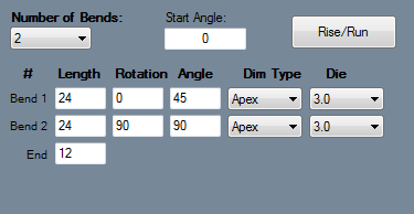
- The number of bends in the part can be chosen from the "Number of Bends" drop down menu. Up to 50 bends can be added to a part.
- To change the starting angle of the part, enter a value in the "Start Angle" field.
- Below all these options, the length, rotation, and angle values can be typed in for each part's bend and the end length. To define length, rotation, angle, or end values, just type the values into the fields.
- The Rise and Run button can be used to generate length and angle values based on the rise and run of a specific length of pipe or tubing.
1.)First place the cursor in the length fields from the second bend and onward.
- Click on Rise and Run
 to open the tool.
 - Type in the rise and run values in the fields so the calculated length and angle values will be generated below.
- Select the Over 90 Degree Bend check box if the measurements are for a length with a bend that exceeds 90 degrees.
- Select the Use Values button
 to bring in the length value for the current bend and the bend angle for the previous bend.
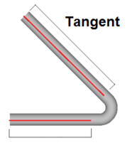
- Each bend will have a Dim Type and Die drop down menu. Dim Type will determine how the part length will be measured for that bend.
- To choose a dimension type, click the drop down menu and select either Apex or Tangent.
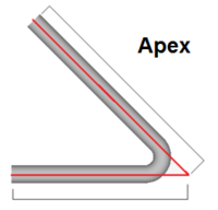
- To change all the dimension types to single type, select the desired dimension type in the Dim Type for the first bend, then select the enter key. Apex will measure to the outside intersection (apex) of the bends two legs. Tangent will measure to the edge of the bends, the tangents, so no bent material will be included in the measurements. *Different dies can be selected for each bend by either clicking any of the 'Die' drop down menus and selecting a die/Custom CLR.
