Cutting Tutorial (Advanced)
In this tutorial you will create cutting sleeves for complex part intersections. It is recommended that you complete the basic Cutting Tutorial before starting this one.
Note: Inches are used as the measurement units throughout this tutorial.
Step 1
Start by launching the Bend-Tech 7x software and opening a new assembly design. This can be done by:
1.) Go to the File menu, select New Assembly.
2.) Click the New Assembly icon ![]() at the top of the window.
at the top of the window.
...OR
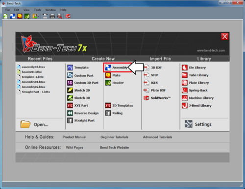
3.) Select the Assembly option from the Task Menu that appears when the software starts up.
Step 2
Before we start, we need to put a few parts together so that we have something to cut.
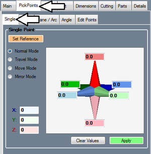
Go to the PickPoints tab and the Single sub-tab.
Step 3
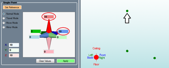
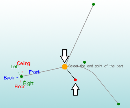
Click the Set Reference button ![]() and click the point at the center of the Tri-Star (this should be the only point on the screen right now). If you successfully select the point, it will turn red.
and click the point at the center of the Tri-Star (this should be the only point on the screen right now). If you successfully select the point, it will turn red.
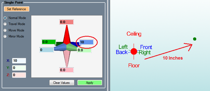
Enter 10 in the darker blue Front field and click Apply. ![]()
Step 4
Click the Clear Values button.
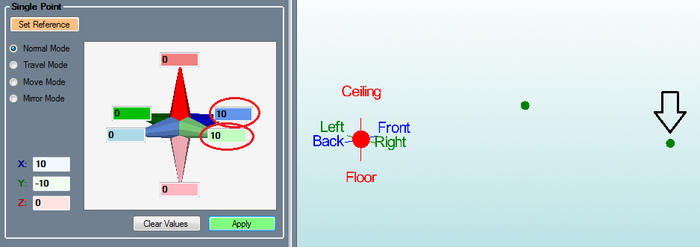
Enter 10 in the darker blue Front field and 10 in the light green Right field.
Click the Apply button.
Step 5
Click the Clear Values button.
Enter 10 in the darker blue Front field and 10 in the darker red Ceiling field.
Click the Apply button.
Step 6
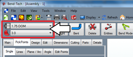
Select a material in the upper left corner of the assembly window. (Note: If there are no materials available, one will need to be created. Refer to the Tube/Pipe Library page for information on how to define tube materials.)
Select a die as well, in the upper left corner, below the material menu.
Step 7
This part will only have 1 bend so click the OK button in the Number of Bends window.
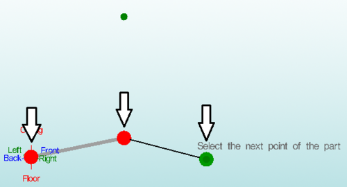
Click the point at the center of the Tri-Star, followed by the first two points we made in the order that we made them.
Click the OK button in the Part Name window.
Step 8
Click the Straight Part button. 
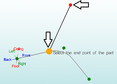
Click the top point, followed by the orange/yellow point on the left side of the bend.
Step 9
Click the light blue colored point at the center of the arc on the display window, followed by the orange/yellow point at the end of the previous part to create the second straight part.
Step 10
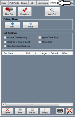
Go to the Cutting tab.
Step 11
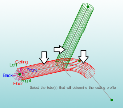
First, click on the top tube, then click on the bottom two tubes below on either side of the first tubes end.
When you are placing cuts, you must first select the section of tube that you want to cut, then any tubes that the first tube should be cut to.
Notice how you had to make two selections for the same part (bottom two). You can only select sections of parts during cutting, so bent parts will need to have their bends and straight sections selected separately.
Step 12
The cut will then be added to the cut list.
Zoom in on the part model to see a better view of the cut outline. The cutting profile will be represented by the blue and black lines.
Step 13
[[File:]]
Now click the New Cut button ![]() again.
again.
Click the section closest to the intersection on the small straight part. Then select the lower section of the top tube, and the two sections on either side of the intersection.
