Dragon Options
"UNDER CONSTRUCTION:THANK YOU FOR YOUR PATIENCE."
Contents
Global Options
General

Default Items
- Default Die: Click on the drop down menu labeled "Default Die:"
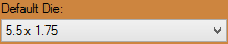 and select a die that you would like to be automatically set when opening a new part.
- Default Tube/Pipe: Click on the drop down menu labeled "Default Tube/Pipe:"
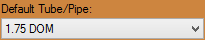 and select a material that you would like to be automatically set when opening a new part.
File Storage
- Data Libraries: Click on the text field labeled "Data Libraries:"
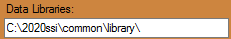 or click the "Browse"
  button to designate a file storage location for your data libraries. This includes dies and material information.
- Parts: Click on the text field labeled "Parts:"
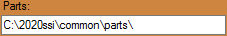 or click the "Browse" button to designate a file storage location for your saved parts.
Tolerances
- Rotation Angle: Click on the drop down menu labeled "Rotation Angle:"
 and select the tolerance for how many decimal places the part's rotation angle will read by default.
- Bend Angle: Click on the drop down menu labeled "Bend Angle:"
 and select the tolerance for how many decimal places the part's bend angle will read by default.
- Lengths: Click on the drop down menu labeled "Lengths:"
 and select the tolerance for how many decimal places or fraction increments the part's length will read by default.
Unit of Measure
- Inches: Select the "Inches"
 option and the part dimensions and information will appear in inches.
- Millimeters: Select the "Millimeters"
 option and the part dimensions and information will appear in millimeters.
Auto-Save Frequency
- Click on the "Auto-Save Frequency"
 drop down menu and select the amount of time it will take for the software to save your progress.
Input / Interface
- Keyboard: Select the "Keyboard"
 option and the method in which you input your information will be constricted to your keyboard.
- Touch Screen: Select the "Touch Screen"
 option and the method in which you input your information will be constricted to your touch screen.
Undo/Redo
- Number of Steps: Click the up and down arrows or key in a number into the "Number of Steps:"
 section to designate a number of undo or redo steps you can take when creating a design.
Misc Options
- Invert Mouse Wheel Zoom: Check the "Invert Mouse Wheel Zoom"
 checkbox and the mouse's zoom function will become inverted (scroll up to zoom out/ scroll down to zoom in).
- Disable Automatic Updates: Check the "Disable Automatic Updates"
 checkbox and the software will no longer attempt to update automatically.
- Display Orientation Axis: Check the "Display Orientation Axis"
 checkbox and the orientation axis will be shown on the display screen.
Main Display
- Normal: Click on the "Normal"
 option and the background in the display screen will be normal by default.
- Custom Color:' Click on the "Custom Color"
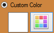 option and choose a default color to assign to the background in the display screen.

- Image: Click the "Image"
 option and browse for a default picture to assign to the background in the display screen.
Machine

Basic Settings
Default Process Order
- Process Order Box: This box will contain the 3 processes that will take place in the fabrication process
 (Etching, Marking and Cutting). To order these in the way you want them, select one from the list and use the Up
  and Down
  arrows to decide the procession.

- Order by Part: Click the "Order by Part"
 option to assign the process order to each individual part.
- Order by Shift: Click the "Order by Shift"
 option to assign the process order to each individual shift.
Misc Options
- Long Travel Minimum: Enter a value in the "Long Travel Minimum"
 text field to indicate the least amount of distance that the machine will travel to still be considered a 'long travel'. A long travel will most likely be when the machine travels from one set of contours to another, or one end of tubing to another.
- Loading Offset: When using a material with a diameter larger than 3 inches, enter a value in the "Loading Offset"
 text field to indicate the offset distance to the end of the tubing.
- Reduce Dead-Zone by Flipping: Check the "Reduce Dead-Zone by Flipping"
 checkbox and the software will automatically flip certain parts to reduce the dead space that would normally lie in between them,
- Reduce Part Shifts: Check the "Reduce Part Shifts"
 checkbox and the software will automatically reduce the amount of shifts needed in a nesting project.
Bend Marks (Default)
- None: Select the "None"
 option if you would not like the bend marks assigned to an action by default.
- Mark: Select the "Mark"
 option if you would like the bend marks to be marked with a marker by default.
- Engrave: Select the "Engrave"
 option if you would like the bend marks to be engraved by default.
End Cuts (Default)
- None: Select the "None" option if you would not like the end cuts assigned to an action by default.
- Cut:' Select the "Cut"
 option if you would like the end cuts to be cut with the machine's plasma cutter by default.
- Mark: Select the "Mark" option if you would like the end cuts to be marked with a marker by default.
Part ID Marking
- Enable Part ID Marking: Check the "Enable Part ID Marking"
 checkbox and your part will be either marked or engraved with the part ID information by default.
- Part ID Font: Click on the "Part ID Font"
 drop down menu to choose the font that the part ID will be marked or engraved in by default.
- Part ID Size: Enter a value in the "Part ID Size"
 text field to designate a size of the part ID lettering. This will be in inches or millimeters depending on what your units of measurement are set to.
- Part ID Location: Enter a value in the "Part ID Location"
 text field to designate a location down the length of the tubing where the part ID will be located by default.
- Mark: Select the "Mark" option if you would like the part ID to be marked with a marker by default.
- Engrave: Select the "Engrave" option if you would like the part ID to be engraved by default.
Saddles (Default)
- None: Select the "None" option if you would not like the saddles assigned to an action by default.
- Mark: Select the "Mark" option if you would like the saddles to be marked with a marker by default.
- Engrave: Select the "Engrave" option if you would like the saddles to be engraved by default.
Cutter Settings

Cutting Tool
- Kerf: Enter the default width of your cut in the "Kerf"
 text field.
- Lift Amount (Short): Enter the height of the lift amount for a short distance travel of the plasma head in the "Lift Amount (Short)"
 text field.
- Lift Amount (Long): Enter the height of the lift amount for a long distance travel of the plasma head in the "Lift Amount (Long)"
 text field.
Corner Fix
- Add Dwell: Click on the "Add Dwell"
 option to ensure that a corner of two contours is cut appropriately by adding a small delay in the cut. The plasma torch will pause momentarily to avoid a cornered radius on what is meant to be a smooth transition between straight cuts.
- Add Line: Click on the "Add Line"
 option to ensure that a corner of two contours is cut appropriately by adding a small line to the cut. This will avoid a delay and a cornered radius on what is meant to be a smooth transition between straight cuts. This is the preferred method.
- None: Click on the "None" option and the software will not add a fix for cornered radii when cutting adjacent contours.
- Min Angle: Enter the minimum angle possible in order to require a corner fix in the "Min Angle:"
 text field.
- Time (milliseconds): When the Add Dwell option is selected, enter the time allotted for a pause in cutting in the "Time (milliseconds)"
 text field.
- Line Length: When the Add Line option is selected, enter the line length allotted for the contour in the "Line Length"
 text field.
Pause for Drops
- Enable Pausing: Check the "Enable Pausing"
 checkbox to cause the plasma torch to pause when finishing a through-cut or cope. This will ensure a clean cut-off.
- Minimum Length: Enter a value in the "Minimum Length:"
 text field which will determine the minimum length needed before a pause can occur on an end cut.
Travel Direction
- Right: Click on the "Right"
 option and the cutting direction will always start from the left and move to the right.
- Left: Click on the "Left"
 option and the cutting direction will always start from the right and move to the left.
Engraver Settings

Engraver Tool:
- Lift Amount (Short): Enter the height of the lift amount for a short distance travel of the engraver head in the "Lift Amount (Short)" text field.
- Lift Amount (Long): Enter the height of the lift amount for a long distance travel of the plasma head in the "Lift Amount (Long)" text field.
Corner Fix
- Add Dwell: Click on the "Add Dwell" option to ensure that a corner of two contours is engraved appropriately by adding a small delay in the etching. The engraver will pause momentarily to avoid a cornered radius on what is meant to be a smooth transition between straight etches.
- Add Line: Click on the "Add Line" option to ensure that a corner of two contours is engraved appropriately by adding a small line to the contours. This will avoid a delay and a cornered radius on what is meant to be a smooth transition between straight etches. This is the preferred method.
- None: Click on the "None" option and the software will not add a fix for cornered radii when engraving adjacent contours.
- Min Angle: Enter the minimum angle possible in order to require a corner fix in the "Min Angle:" text field.
- Time (milliseconds): When the Add Dwell option is selected, enter the time allotted for a pause in engraving in the "Time (milliseconds)" text field.
- Line Length: When the Add Line option is selected, enter the line length allotted for the contour in the "Line Length" text field.
Marker Settings

Marking Tool:
- Lift Amount (Short): Enter the height of the lift amount for a short distance travel of the engraver head in the "Lift Amount (Short)" text field.
- Lift Amount (Long): Enter the height of the lift amount for a long distance travel of the plasma head in the "Lift Amount (Long)" text field.
Corner Fix
- Add Dwell: Click on the "Add Dwell" option to ensure that a corner of two contours is marked appropriately by adding a small delay in the marking. The marker will pause momentarily to avoid a cornered radius on what is meant to be a smooth transition between straight marks.
- Add Line: Click on the "Add Line" option to ensure that a corner of two contours is marked appropriately by adding a small line to the contours. This will avoid a delay and a cornered radius on what is meant to be a smooth transition between straight marks. This is the preferred method.
- None: Click on the "None" option and the software will not add a fix for cornered radii when marking adjacent contours.
- Min Angle: Enter the minimum angle possible in order to require a corner fix in the "Min Angle:" text field.
- Time (milliseconds): When the Add Dwell option is selected, enter the time allotted for a pause in marking in the "Time (milliseconds)" text field.
- Line Length: When the Add Line option is selected, enter the line length allotted for the contour in the "Line Length" text field.
Factory Settings

These settings will not be accessible to users by default.
Output

Rotation
The rotation settings control how rotation values are displayed in the results table. Rotation can be measured in incremental or absolute terms. Each rotation angle range can also be chosen.
- Incremental: Select the "Incremental:"
 option and rotation angles will start from the end of the previous bend's rotation.
- Absolute: Select the "Absolute:"
 option and rotation angles will always start from the very beginning of the angle scale.

- Angle Scale: The rotation scale will determine what the rotation angles will range between. The rotation scale will show where the angle measurements begin and where they end. Choose a rotation scale by clicking on one of the scale options. The rotation scales available are 0 - 360, 360 - 0, (-180) - 180, and 180 - (-180). The 0 - 90 - 0 - 90 - 0 and 0 - 90 - 0 - 90 - 0 Reversed options will be added when the Absolute option is chosen.
Length/Location
The length/location setting will determine how the bend location will be calculated in the results table.
- Distance from Start: Select the "Distance from Start"
 option and bend locations will be measured from the starting edge of the tube.
- Distance from End: Select the "Distance from End"
 option and bend locations will be measured from the ending edge of the tube.
- Length of Straight Tube: Select the "Length of Straight Tube"
 option and bend location values will be the amount of straight tube between each bend.
- Table Location: Select the "Table Location"
 option and bend locations will be based on index table values. If this option is used, the "Offset Distance"
  between the table and the bend will need to be supplied as well as scale "Table Length"
  . Check the "Indexing Begins at Die"
  option if the scale begins at the die.
- Dimension Location:
 This option determines where the bend location marks will be placed in reference to the bend. Bend locations can be placed at the start, center, or end of each bend.
Misc Display Options
- Display parentheses () for negative values: Check the "Display parentheses () for negative values"
 checkbox and all negative values in the output results table will be surrounded by parentheses.
- Display Degree Symbol: Check the "Display Degree Symbol"
 checkbox and the degree symbol will be shown in the output results table.
- Display Feet/Meters: Check the "Display Feet/Meters"
 checkbox and the lengths of each tube including overall lengths will be shown as feet or meters in the output results table.
- Display Minutes/Seconds: Check the "Display Minutes/Seconds"
 checkbox and the minutes and/or seconds for fabrication time will be shown in the output results table.
- Display Spring Angles: Check the 'Display Spring Angles"
 checkbox and the part's spring angles will be shown in the output results table.
- Display Length of Bend: Check the "Display Length of Bend"
 checkbox and the lengths of each bend on a part will be shown in the output results table.
Custom Part

Defaults
- Cut-Off Color: Select the color that will be assigned to the section of cut-off added to the part by clicking the color box next to the "Cut-Off Color:"
 heading.
- Tri-Star Scale: Enter a value in the "Tri-Star Scale:"
 text field to assign a size to the scale of the Tri-Star. 1=100% (Normal Size), 2=200% (Twice the Normal Size).
- Dimension Size: Enter a value in the "Dimension Size:"
 text field to assign a size to the dimensions shown on your parts. 1=100% (Normal Size), 2=200% (Twice the Normal Size).
- Notes: Enter information about these settings in the "Notes:"
 text field.

Misc Custom Part Options
- Reverse Rotation: Check the "Reverse Rotation"
 checkbox to ensure that the rotation settings are shown in reverse.
Features to Display
These settings will determine the kind of features that will be displayed on the part model in any of the single part design interfaces. Click the check boxes next to the features you want to have shown.
- Dimensions: Length measurement values will be displayed on the part lengths.
- Cut-Off: If any cut-off is added to the part, it will be represented on the part display.
- Apex Guides: For each bend, guidelines will extend from the part model to the verification points.
- Tri-Star: The axis will be shown on the graphical display.
- Verification Points: Points will be displayed at the apex of each bend.
- Bend Highlight: The current bend will be highlighted in red on the 3D part model.
Cut-Off
- The default cut-off start and end values can be defined here. Each new part will automatically have these cut-offs initially applied.
CAD

Dimensions
- Text Size: Enter the default text size for when you create dimensions within a project. This will be set to 1 be default.
- Ext. Offset: Enter the distance that straight extensions will protrude from placed dimensions. This will be set to 0 by default.
- Ext. Standoff: Enter the distance from the dimension points that straight sections will start from. This will be set to 0 by default.
- Arrow Width: Enter the width of your arrows for placed dimensions. This will be set to 0.5 by default.
- Arrow Length: Enter the length of your arrows for placed dimensions. This will be set to 1 by default.
- Arrow Type: Choose the arrow type for placed dimensions. Options are None, Single, Double, Closed, and Solid. This will be set to Double by default.
- Angle Tolerance: Choose how specific your angle dimensions will read out when placed. This will be set to 'n' by default.
- Tolerance: Choose the tolerance of either fractions or decimals for your horizontal, vertical and linear placed dimensions. This will be set to 'Fraction n/16' by default.
Holes - Default Values
- Round Select the Round option and you will be able to adjust the default width of round holes in the corresponding Width: value field. This will be set to 1 by default.
- Square Select the Square option and you will be able to adjust the default width, angle and corner radius of square holes in the corresponding Width:, Angle: and Corner Radius:' value fields. These will be set to 1, 0 and 0 by default.
- Rectangle Select the Rectangle option and you will be able to adjust the default width, angle, height and corner radius of rectangular holes in the corresponding Width:, Angle:, Height: and Corner Radius: value fields. These will be set to 1, 0, 2 and 0 by default.
- Oval Select the Oval option and you will be able to adjust the default width, angle and height of oval holes in the corresponding Width:, Angle: and Height: value fields. These will be set to 1, 0 and 2 by default.
- Ellipse Select the Ellipse option and you will be able to adjust the default width, angle and height of ellipse holes in the corresponding Width:, Angle: and Height: value fields. These will be set to 1, 0 and 2 by default.