Difference between revisions of "Sketch 3D"
| (One intermediate revision by the same user not shown) | |||
| Line 2: | Line 2: | ||
__NOTOC__ | __NOTOC__ | ||
[[File:sketch3d_1.png|right|500px]] | [[File:sketch3d_1.png|right|500px]] | ||
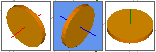
| − | Sketch 3D allows parts to be created on a three dimensional plane. Parts can be designed by clicking directly on the part display and drawing out each length and/or by giving the straight length and angle values in the design panel. | + | *Sketch 3D allows parts to be created on a three dimensional plane. Parts can be designed by clicking directly on the part display and drawing out each length and/or by giving the straight length and angle values in the design panel. |
| − | + | ==Selection== | |
[[File:xyz_part_2.png|150px|left]]'''To create a Sketch 3D Part:''' | [[File:xyz_part_2.png|150px|left]]'''To create a Sketch 3D Part:''' | ||
| − | 1.) Go to the '''File''' menu, select '''New''', then select '''Tube'''. In the '''Create New''' menu, | + | '''1.)''' Go to the '''File''' menu, select '''New''', then select '''Tube'''. In the '''Create New''' menu, select on the '''Sketch 2D''' option. |
| − | 2.) | + | '''2.)''' Select the '''New Part''' icon and select the '''Sketch 3D''' option in the'''Create New''' menu. |
'''...OR''' | '''...OR''' | ||
| − | 3.) Select the '''Sketch 3D''' option from the [[View#Task Menu|Task Menu]] that appears when the software starts up, when all designs are closed, or through the view menu. | + | '''3.)''' Select the '''Sketch 3D''' option from the [[View#Task Menu|Task Menu]] that appears when the software starts up, when all designs are closed, or through the view menu. |
| Line 22: | Line 22: | ||
| − | + | ==Design== | |
| − | Once '''Sketch 3D''' is selected, a new part design window will open. If a default die and material have not been set, a die and material must be chosen before designing the part. If necessary, '''choose a material, die, and/or machine''' in the Die and Material tab. Once a die and material are selected, the Sketch 3D part design section will appear. | + | *Once "'''Sketch 3D'''" is selected, a new part design window will open. If a default die and material have not been set, a die and material must be chosen before designing the part. If necessary, '''choose a material, die, and/or machine''' in the Die and Material tab. Once a die and material are selected, the Sketch 3D part design section will appear. |
[[File:sketch3d_2.png|right|350px]] | [[File:sketch3d_2.png|right|350px]] | ||
| − | Next, the part can be designed by drawing out the part lengths in the part display and/or typing in length and angle values. | + | *Next, the part can be designed by drawing out the part lengths in the part display and/or typing in length and angle values. |
| − | '''To design a part''', start by | + | *'''To design a part''', start by selecting a point in the display area where the first length of the part will begin. Once this point is selected, a light blue line will be connected to this point (as shown to the right). The length of the current part section will be generated at the end of this line. |
| − | The leg length and XY coordinates of the start and end of the current length will be generated above the part design area. | + | *The leg length and XY coordinates of the start and end of the current length will be generated above the part design area. |
| Line 45: | Line 45: | ||
[[File:sketch3d_4.png|right|350px]] | [[File:sketch3d_4.png|right|350px]] | ||
| − | The next point that is | + | *The next point that is selected will be the end point of the first straight length of tube. After this second point is chosen, the display will show the part's first straight length in the chosen material. The light blue line will now be attached to the end point of this length. Continue this process of choosing the start and end points until the part is complete. |
| − | As new lengths and bends are drawn, the lengths, rotations, and angles will be generated in the columns on the left of the screen. Each bend and the last straight length will have its own row. | + | *As new lengths and bends are drawn, the lengths, rotations, and angles will be generated in the columns on the left of the screen. Each bend and the last straight length will have its own row. |
| − | These can be edited at any point in the design process. Adjust the lengths and angles by entering new values in the text fields. | + | *These can be edited at any point in the design process. Adjust the lengths and angles by entering new values in the text fields. |
| − | While designing the part, the axis that the grid is upon can be adjusted using the axis selection buttons in the upper left corner of the part display. These icons will rotate with the part model to show how the grid will be shown when using that specific option. | + | *While designing the part, the axis that the grid is upon can be adjusted using the axis selection buttons in the upper left corner of the part display. These icons will rotate with the part model to show how the grid will be shown when using that specific option. Select one of these options [[File:sketch3d_5.png]] ('''XY, YZ, and XZ respectively''') to adjust the grid's plane. |
| − | '''To delete the last straight length and bend''', click the '''Delete Last''' | + | *'''To delete the last straight length and bend''', click the '''Delete Last''' [[File:delete_last.png]] button. |
| − | Once the '''part is complete''', | + | *Once the '''part is complete''', select the "'''Finish'''" [[File:finish_part1.png]] button. Note: This is temporary. Edits can still be executed after a design session is stopped. This will only stop further lengths/bends from being drawn. |
| − | To completely restart the part design, | + | *To completely restart the part design, select the "'''Start Over'''" [[File:start_over1.png]] button. "'''Caution: This will completely delete the part design and cannot be undone.'''" |
| − | Each bend can be also be assigned a die by either selecting the bend number in the bend list and selecting a die or custom CLR from the '''Die''' drop down menu. Each bend can also be assigned a dimension type by selecting either Apex or Tangent from the '''Dim Type''' drop down menu. Apex will measure to the outside intersection (apex) of the bends two legs. Tangent will measure to the edge of the bends, the tangents, so no bent material will be included in the measurements. See images below. | + | *Each bend can be also be assigned a die by either selecting the bend number in the bend list and selecting a die or custom CLR from the '''Die''' drop down menu. Each bend can also be assigned a dimension type by selecting either Apex or Tangent from the '''Dim Type''' drop down menu. |
| + | *'''Apex''' will measure to the outside intersection (apex) of the bends two legs. '''Tangent''' will measure to the edge of the bends, the tangents, so no bent material will be included in the measurements. See images below. | ||
::[[File:apex.png|200px]] [[File:tangent.png|186px]] | ::[[File:apex.png|200px]] [[File:tangent.png|186px]] | ||
| − | The '''size of each cell''' in the the grid overlay on the part display can be adjusted by changing the number in the '''Grid Spacing''' field. [[File:grid_spacing.png]] | + | *The '''size of each cell''' in the the grid overlay on the part display can be adjusted by changing the number in the "'''Grid Spacing'''" field. [[File:grid_spacing.png]] |
| − | The grid overlay can also be toggled on and off using the '''Grid''' | + | *The grid overlay can also be toggled on and off using the "'''Grid'''" [[File:grid.png]] button. While the grid is on/activated, the start and end points of the part will be snapped to this grid during the design process. |
Latest revision as of 10:11, 22 September 2014
Bend-Tech 7x Wiki :: Sketch 3D

- Sketch 3D allows parts to be created on a three dimensional plane. Parts can be designed by clicking directly on the part display and drawing out each length and/or by giving the straight length and angle values in the design panel.
Selection

1.) Go to the File menu, select New, then select Tube. In the Create New menu, select on the Sketch 2D option.
2.) Select the New Part icon and select the Sketch 3D option in theCreate New menu.
...OR
3.) Select the Sketch 3D option from the Task Menu that appears when the software starts up, when all designs are closed, or through the view menu.
Design
- Once "Sketch 3D" is selected, a new part design window will open. If a default die and material have not been set, a die and material must be chosen before designing the part. If necessary, choose a material, die, and/or machine in the Die and Material tab. Once a die and material are selected, the Sketch 3D part design section will appear.

- Next, the part can be designed by drawing out the part lengths in the part display and/or typing in length and angle values.
- To design a part, start by selecting a point in the display area where the first length of the part will begin. Once this point is selected, a light blue line will be connected to this point (as shown to the right). The length of the current part section will be generated at the end of this line.
- The leg length and XY coordinates of the start and end of the current length will be generated above the part design area.

- The next point that is selected will be the end point of the first straight length of tube. After this second point is chosen, the display will show the part's first straight length in the chosen material. The light blue line will now be attached to the end point of this length. Continue this process of choosing the start and end points until the part is complete.
- As new lengths and bends are drawn, the lengths, rotations, and angles will be generated in the columns on the left of the screen. Each bend and the last straight length will have its own row.
- These can be edited at any point in the design process. Adjust the lengths and angles by entering new values in the text fields.
- While designing the part, the axis that the grid is upon can be adjusted using the axis selection buttons in the upper left corner of the part display. These icons will rotate with the part model to show how the grid will be shown when using that specific option. Select one of these options
 (XY, YZ, and XZ respectively) to adjust the grid's plane.

- To delete the last straight length and bend, click the Delete Last
 button.
- Once the part is complete, select the "Finish"
 button. Note: This is temporary. Edits can still be executed after a design session is stopped. This will only stop further lengths/bends from being drawn.
- To completely restart the part design, select the "Start Over"
 button. "Caution: This will completely delete the part design and cannot be undone."
- Each bend can be also be assigned a die by either selecting the bend number in the bend list and selecting a die or custom CLR from the Die drop down menu. Each bend can also be assigned a dimension type by selecting either Apex or Tangent from the Dim Type drop down menu.
- Apex will measure to the outside intersection (apex) of the bends two legs. Tangent will measure to the edge of the bends, the tangents, so no bent material will be included in the measurements. See images below.


- The size of each cell in the the grid overlay on the part display can be adjusted by changing the number in the "Grid Spacing" field.

- The grid overlay can also be toggled on and off using the "Grid"
 button. While the grid is on/activated, the start and end points of the part will be snapped to this grid during the design process.