Difference between revisions of "SolidWorks Import Tutorial II"
| Line 1: | Line 1: | ||
=="'''UNDER CONSTRUCTION: TNANKS FOR YOUR PATIENCE'''"== | =="'''UNDER CONSTRUCTION: TNANKS FOR YOUR PATIENCE'''"== | ||
| − | + | __NOTOC__ | |
==Things To Know== | ==Things To Know== | ||
Revision as of 08:50, 18 September 2014
"UNDER CONSTRUCTION: TNANKS FOR YOUR PATIENCE"
Things To Know
- This tutorial will step you through the process of exporting a file from SolidWorks and importing it into Bend-Tech. As you walk through this tutorial, procedures are designed based on your knowledge of earlier procedures. Because of this, it is very important that you carefully step through this guide, understanding everything along the way.
A few key items need to be covered before starting the step-by-step instructions of the tutorial. It is very important you completely understand these items:
Centerline & Apex:
Centerline: In the Bend-Tech environment we are working exclusively with the centerline of a part, as compared to the inside or outside.
Apex: The bend locations are defined exclusively with the apex. Our definition of apex is the intersection of the straight tubes as if there wasn’t a radius.
Create Parts: It is possible to create parts in the single part and assembly interfaces of Bend-Tech SW, however, this guide focuses on using part geometry within SolidWorks™ to export into Bend-Tech SW.
Installation: You must have both SolidWorks™ and Bend-Tech SW loaded on the same computer. If installed correctly, you should find a menu selection in SolidWorks™ labeled Bend-Tech. This menu will only be available in SolidWorks™ Part mode and will not be seen in the Assembly mode of SolidWorks™.
Bend-Tech SE vs. SW: Bend-Tech SW contains all the functionality and features of Bend-Tech SE, as well as the ability to import parts directly from SolidWorks™. Any information available for Bend-Tech SE also applies to Bend-Tech SW.
Tutorial
Settings
- 1. To begin, start up the "Bend-Tech 7x" program.
- 2. Before starting, we must first adjust some settings. Go up to the Tools menu in the main menu bar. Click SW Plugin Settings in the drop down menu. In the SW Plugin Settings window
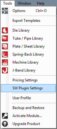

- 3. In the SW Plugin Settings window, make sure Manual Import is the only selected option under the Import Settings section. If not, click the circle next to Manual Import to set it as the SolidWorks™ import method. If any changes were made, click the Save button and then click Close.
 Bend-Tech SE vs. SW: Bend-Tech SW contains all the functionality and features of Bend-Tech SE, as well as the ability to import parts directly from SolidWorks™. Any information available for Bend-Tech SE also applies to Bend-Tech SW.
SolidWorks
- 1. To be able to go through this tutorial, you must have a completed SolidWorks part file available. If not, create a part in SolidWorks™ and come back to this tutorial before continuing on.
- 2. Once a part is ready, ensure that both SolidWorks™ and Bend-Tech are both open and running.
- 3. In SolidWorks™, select either the 3D Sketch or Sweep of the part from the Features list on the left side of the frame as shown below. Once selected the sweep or 3D sketch name will be highlighted in blue.
- 4. Once the sketch or sweep line has been selected, go up to the top left of the SolidWorks window and place your cursor over the right pointing arrow to access the menu bar. In the menu bar, go to the Bend-Tech option and click on Process Bend Info.

- 5. Once Process Bend Info has been selected, the Send To Bend-Tech panel will be opened on the left side of the window. Depending on what kind of feature you selected (3D Sketch or Sweep), it will be shown in either the Feature Selection or Sketch Selection box. Make sure that the listed feature is correct, click on it to select it, then click the green check button.


Part Definition
Now to back to the Bend-Tech window. We are now going to bring the part information into Bend-Tech. To do so, either click on the SolidWorks™ icon in the icon toolbar or go to File --> Import --> SolidWorks.


A small window prompting you to choose a material for the part will appear. Click the drop down menu and select an appropriate material from the list. Once a material has been selected here, a chart containing the name, type, width, wall thickness, and weight of the material will be shown below. To select the material and continue, click the OK button.
If the material cannot be successfully tracked and imported, a message box (shown below) will appear. In this case, you need to manually import the part in the import window. Click Yes to open the Import interface. See the SolidWorks Tutorial - Part Definition Section for a step by step Import walkthrough. If you do not see this message box, proceed to the next step.
Once the part has been successfully imported, automatically or manually, the Part Details window and an XYZ Part design window will be opened. In the XYZ Part design window, the part can be adjusted further, saved, or a setup sheet for the part can be printed. The import process is complete. Now let's move on to the Part Details window.
In the Part Details window, the top part of the window is occupied by a text box containing information about the part. If necessary, you can type directly in this area to either change or add new information.
The information and formatting displayed here is determined by the template that is currently in use. To change templates, select a new template from the drop down menu below Export Template in the bottom right corner.
Click the circle next to LRA to view the LRA table for the part instead of the export template information.
While you're still in LRA mode, check the box next to Reversed LRA. The LRA table will now be reversed completely.
File:ReversedLRA.jpg File:LRAReversed.jpg
Click the circle next to Custom Details to switch it back to the export template again. We are now going to add some cut-off lengths. In the Edit Part section, enter 5 into both the Cut-Off Start and Cut-Off End fields. Notice how the cut length (if included in the template) will adjust to compensate for these values. The lengths in the LRA table (while in either mode) will also be affected by any values entered here.
Click the Copy button. The information shown (only export template) in the part details area will be copied to your clipboard and can be pasted anywhere.