Difference between revisions of "Tools"
| Line 33: | Line 33: | ||
| − | = | + | [[File:j_bend_lib.png|70px|link=J-Bend Library]] <h3>[[J-Bend Library]]</h3 |
The J-Bend Library stores all J-Bends that can be used to create headers. The left side of the screen is occupied by a list of all J-Bends in the library. Once a J-Bend name has been selected in the list, its information will be displayed to the right under J-Bend Details. | The J-Bend Library stores all J-Bends that can be used to create headers. The left side of the screen is occupied by a list of all J-Bends in the library. Once a J-Bend name has been selected in the list, its information will be displayed to the right under J-Bend Details. | ||
| − | |||
| − | |||
| − | |||
| − | |||
| − | |||
| − | |||
| − | |||
| − | |||
| − | |||
| − | |||
Revision as of 15:47, 29 May 2014
Bend-Tech 7x Wiki :: Main Menu Bar :: Tools
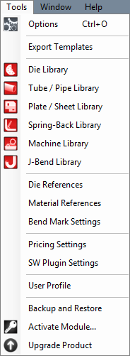
In the Tools menu, the options menu, Tube/Pipe Library, Plate/Sheet Library, Die Library, Machine Library, J-Bend Library, Price Settings, Primary Templates, and the Export Template menu can be accessed.
Options
Click 'Options' to access the options/settings menu. Follow the "Options" link for further information on each tab in the Options menu.
Export Template
In the Export Template Design menu, the designs of Export Templates can be set up. Follow the "Export Template" link for further information on designing export templates.

Die Library
The die library stores all of the dies that can be used. On the left side of the die library, a list of all available dies is show below 'Die List'. To the right of the list, Die details, die limitations, and user defined definitions are shown.

Tube/Pipe Library
The Tube/Pipe Library holds all the materials that can be used to create single parts. On the right side of the Tube/Pipe Library window, under 'Material List', is the list of each available material. To the right of this list is the area where tube/pipe material information will be shown.
Plate/Sheet Library
The Plate/Sheet Library holds all materials that can be used to create a plate. On the left side of the window, under 'Material List', a list of all plate/sheet materials is shown. On the far right side of the window, a list of bending radii for the currently selected material is shown below 'Bending Radius List'.

J-Bend Library</h3
The J-Bend Library stores all J-Bends that can be used to create headers. The left side of the screen is occupied by a list of all J-Bends in the library. Once a J-Bend name has been selected in the list, its information will be displayed to the right under J-Bend Details.
Machine Library
The Machine Library stores all machines that can be used to apply settings to and simulate the bending of a single part. At the top of the window, under 'Current Machine' there is a drop down menu containing a list of all machines in the library. Once a machine has been selected in this list, its details will be shown in the tabs below. Any settings chosen here will applied to the current part when the machine is chosen from the 'Machine' drop down menu in the Settings tab in a single part design.
View/Edit: To view and/or edit a machine's information, first select the machine from the drop down menu at the top of the window. Once a machine is chosen, each tab below will show that specific machine's settings and defaults. Follow the instructions below to change any of these machine details.
- Defaults: All settings in this tab are only defaults and can be changed, if necessary, after the machine is added to the part.
To select a default die, click the drop down menu below 'Default Die' and select a die from the list.
To select a default material, click the drop down menu below 'Default Material' and select a material from the list.
To change the units the machine uses, click the circle next to 'Inches' or 'Millimeters'.
To add or change the machine's default note, enter a new note by typing in the field below 'Default Note'.
To adjust the default cut-off lengths, enter values into the 'Start End' and/or 'Far End' fields.
- Output Results: In the Output Results tab, the rotation type and scale, length/location settings, and tolerance levels for rotation angles, bend angles, and lengths can be set. The setup sheet and part results options are also available to choose here.
Under 'Rotation', either Incremental or Absolute can be chosen by clicking the circle next to the option. Incremental means the rotation angles will start at the end of the rotation before it. Absolute means the rotation angles will always start from the beginning of the rotation range at each new rotation. Below Incremental/Absolute, there is a list of rotation scales. Choose either -180 to 180, 180 to -180, 0 to 360, or 360 to 0 by clicking the circle next to the option.
Under 'Length/Location', the method of measuring the lengths of tube can be chosen. Choose either Distance from End, Distance from End- Reversed, or Length of Straight Tube by clicking the circle next to the option. If an index table is in use and there is any offset in between the machine and the table, the offset distance can be entered into the Offset Distance (Index Table) field.
Under 'Tolerance', the decimal tolerance for rotation and bend angle can be adjusted. To change either of these, select an option from the drop down menu below Rotation Angle or Bend Angle. Each 'n' represents a digit place.
Under 'Setup Sheets', printing options for the setup sheet can be adjusted. Check the box next to 'Print Transition Sheet' to print out a list of each movement (location, rotation, angle) made for each bend on the setup sheet. Check the box next to 'Print Tri-Star' to print the XYZ tri-star with the part image on the setup sheet. Check the box next to 'Print Design Instructions' to include the part results table on the setup sheet. Check the box next to 'Print Dimensions' to include the measurement lines and values on the part image on the setup sheet.
Under 'Part Results', settings specific to the results table can be adjusted. Check the boxes next to 'Display Length of Bend', 'Display Degree Symbol', and/or 'Display Spring Angles' to include any of these in the results table. Check the box next to 'Display parentheses () for negative values' to surround any negative values in the result table with parentheses.
- Design Input:
Under Reverse Design - Length, either Incremental or Absolute - Start, End, Center, Start (Reversed), End (Reversed), or Center (Reversed) can be selected by clicking the circle next to the option. This will determine how lengths will be measured when creating a Reverse Design part.
Under Reverse Design - Rotation, Incremental, Incremental - Reversed, or Absolute: 0 to 360, 360 to 0, 180 to -180, or -180 to 180 can be chosen by clicking the circle next to the option. This will determine how and on which scale the rotations will be measured when creating a Reverse Design part.
- Simulation:
To adjust the Travel, Rotation, Bending and/or Animation speed, click, hold and drag the pointer back and/or forth to adjust the speed level.
To choose the type of machine, click the drop down menu below 'Bender:' and select a machine type from the list.
To change the quality of the simulation, click the drop down menu below 'Quality' and select a quality level from the list.
Pricing Settings
Once the price settings have been set up, the total cost of a part, plate, or assembly, including labor, setup time, time per bend, and cost per unit, can be determined.
- General: In the General tab, the rate per hour, mark-up labor percent, and mark-up percent for material can be set up. To change or add the rate per hour, enter a value into the 'Rate per Hour' field. To change or add the mark-up labor percentage, enter a numerical value into the 'Mark-up Labor (%)' field. To change or add the mark-up material percentage, enter a numerical value in the 'Mark-up Material (%)' field. For either mark-up labor or material, it is unnecessary to add a percent symbol.
- Die: In the Die tab, the time per bend and setup can be applied to each die that has been added to the die library. To add the setup and bend time to a certain die, click on the die in the Die List to select it. Once a die has been selected, the Time per Bend and Time per Setup fields will be available. Enter the how many minutes it takes to bend a single bend with the chosen die in the 'Time per Bend (in minutes)' field. Enter the how many minutes it takes to setup the die in the 'Time per Setup (in minutes)' field. Once these values have been entered, click the 'Apply' button to save.
- Material: In the Material tab, the cost per unit and time per cut and setup for straight cutting, fishmouthing/notching, and welding can be set up. To change or add any of the available settings for a specific material, click on the material name in the Material List to select it. Once selected, all cost/time fields will be available. Enter the material's cost per unit in the 'Cost per Unit' field below Material Cost. Enter the amount of minutes it takes to cut and setup the material for straight cuts in the 'Time per Cut' and 'Time per Setup' under Straight Cutting. Enter the amount of minutes it takes to cut and setup the material for fishmouth or notch cuts in the 'Time per Cut' and 'Time per Setup' fields below Fishmouthing or Notching. Enter the amount of minutes it takes to weld a single node and setup the material for welding in the 'Time per Node' and 'Time per Setup' fields below Welding. Once the needed costs and/or times have been entered, click the 'Apply' to save these settings.
- Plate: In the Plate tab, the cost per unit can be set up. To change or add the cost per square unit, click on the plate name in the Material List to select it. Enter the cost per square unit of plate material into the 'Cost per Square Unit' field. The units used here will be determined by which units were chosen for the plate when it was added to the Plate Library. Click the 'Apply' button to save the entered value.
User Profile
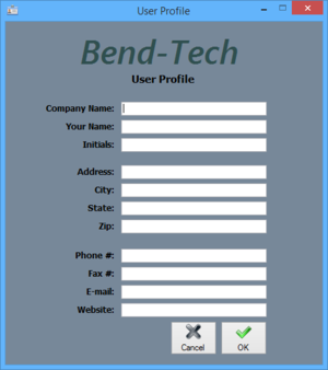
Entering information in the User Profile allows the user to have their information attached to the software. The initials given here will be printed on any setup sheets that are printed out.
To add or change any of the user profile information, simply enter a new definition for any of the available fields. Click 'OK' to save and exit. Click 'Cancel' to exit without saving any entered information.
