- Our Bend-Tech Dragon software works alongside with Bend-Tech Industrial and is meant to prep the part(s) or project before production using the Dragon machine.
- The "Dragon Task Menu" consists of four options for creating new parts. Bend-Tech Dragon will also allow transfers from Bend-Tech Industrial and other designers.
We strongly recommend that no other programs be running while using our Dragon software/Dragon machine.

Bent Part
- Clicking on this option will allow the user to create a new "Custom Part" including bends and end cuts. It has many of the same characteristics of our "Custom Part" designer, except with a few additions that users will need in order to add copes or mitered cuts on the ends of the tubing.
Action Tabs
Die & Material
- The "Die & Material" section is where users will select the die which will be assigned to bend the part and the material associated with that die.
- The section to the right of these drop down menus will show the information associated to the current die and material.
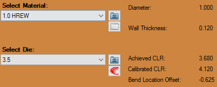
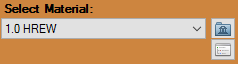
Select Material
- The Select Material:" drop down menu is where users will choose their desired material.
Click the small Folder icon  here to access your material library and select your material that way.
Click on the small Sort List icon  here to access your materials by your sorted lists.
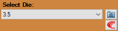
Select Die
- The "Select Die:" drop down menu is where users will choose their desired die.
Click the small Folder icon here to access your die library and select your die that way.
Click on the small Custom Radius icon  here to add a custom radius specifically designed for the bends in this part. (NOTE) This will not be added to your die library as a valid die option.
Number of Bends
- The "Number of Bends"
 drop down menu is where users will select the number of bends contained in the intended part. This must be selected before entering information into the Inputted Information section.
Start Angle
- Enter a start angle for the first leg of the part by entering a value in the "Start Angle:"
 value field.
Verify
- Select the "Verify"
 button to check key distances and angles of your part in our verify window.
Cutting
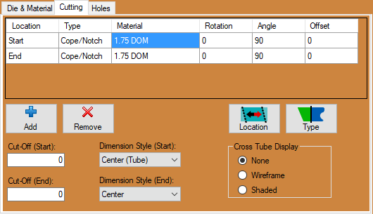
The "Cutting" tab will determine the cuts on the starting of the tube and the cuts on the ending of the tube. Multiple cut nodes can be preformed to create any number of unique cut profiles.
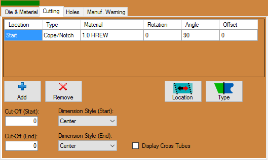
- Click on the "Add"
 button to add a new cut to the tube/pipe created.
- With a cut selected from the cut list, click on the "Remove"
 button to remove it from the design.
- The "Location" section shows the location of the newly added cut (Start, or End). This location can be switched simply by clicking on the "Location"
 button or by double clicking the list item section itself.
- The "Type" section gives users the option to choose a type of cut from "Cope/Notch" and "Miter". This type of cut can be switched simply by clicking on the "Type"
 button or by double clicking the list item section itself.
- The "Material" section is a drop down menu that will give users the option to choose the size of tube that the current part will be intersecting with. This will adjust the size of the end cope(s) or miter cut profile(s).
- The degree of rotation entered into the "Rotation" field will determine the rotation of the cut on either the start or end of the tube.
- The degree of angle entered into the "Angle" field will determine the angle of the cut on either the start or end of the tube.
- The degree of offset entered into the "Offset:" field will determine how the intersecting tube is offset from the start or end of the tube.
- The value entered into the "Cut-Off (Start):" field will determine how many extra units (inches or millimeters) of tubing will be added to the start of the tube.
- The value entered into the "Cut-Off (End):" field will determine how many extra units (inches or millimeters) of tubing will be added to the end of the tube.
- The "Dimension Style" gives the user the option to choose the dimension of the cope/notch or miter from "Inside", "Center", "Outside" and "Center (Tube)" dimensions as it pertains to the diameter of the tubing.
Center - part is measured from the center of the cut profile.
Inside - part is measured from the shortest point of the cut profile.
Outside - part is measured from the longest point of the cut profile.
Center (Tube) - part is measured from the center of the CROSS TUBE. NOTE: Since multiple cross tube sizes can be defined for a cut profile, only the cross tube applied first will be used to determine the dimension location when using this method.
- Checking the "Display Cross Tubes" check box will cause the intersecting cross tube to appear in the display screen.
Holes
Shape
Round: Select Round, enter a diameter in the Width: field, and use the Hole Location section to determine where the round hole will be placed on the tube.
Oval: Select Oval, enter a width and height in the Width: and Height: fields, and use the Hole Location section to determine where the oval hole will be placed on the tube.
Square: Select Square, enter a width in the Width: field. If you want to automatically round the corners of the square, you can enter a value in the Corner: field. Entering 0 in the Corner field will result in square corners. Then, use the Hole Location section to determine where the square hole will be placed on the tube.
Ellipse: Select Ellipse and enter a width and height in the Width: and Height: fields, and use the Hole Location section to determine where the elliptical hole will be placed on the tube.
Rectangle: Select Rectangle and enter a width and height in the Width: and Height: fields and enter a value in the Corner: field. Entering 0 in the Corner field will result in square corners. Then, use the Hole Location section to determine where the rectangular hole will be placed on the tube.
Hole Dimensions
Width: Enter the width of the hole in this text field.
Height: Enter the height of the hole in this text field.
Corner: Enter the corner radius of the hole in this text field.
Hole Location
Leg: Choose the leg on which the hole will be placed in this text field.
Distance: Enter the distance that the hole will be from the start of the selected leg in this text field. Note: If Leg 1 is selected, the distance will be from the start of the tube. If any other leg is selected, the distance will take place from the end of the leg's previous bend.
Rotation: Enter the rotation of the hole in this text field. This rotation value will be based from the previous bend's inside radius.
Travel Check this check box and the location of the hole placed will be based from the start of the tube and not the distance from the previous bend.
Opposite Check this check box and the hole placed will be located on both sides of the tubing at the designated distance.
Action Buttons
Add Click the Add button and enter the information for the hole details in the list to create the hole in your design.
Remove Click the Remove button and the selected hole will be removed from the list and from the design.
Copy Click the Copy  button and the selected hole be copied and duplicated in the holes list. Doing this will make it much easier to set a similar hole in the design if you only need to change a few of the dimensions, or location settings.
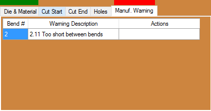
Manuf. Warning
The "Manufacturing Warning" tab will show the user if the part that was created is or isn't a valid part ready for production.
When your part is ready for special designed holes, text and other contours, simply transfer the part to our flat layout interface by using the "Edit Flat"  button at the top of the screen. To learn more about this interface, scroll down to the "Custom Design" section of this Wiki.
You may also skip the transfer to Custom Design step and send your part directly to the "Nesting" interface by clicking on the "Nest Part"  button.
Straight Part
- Clicking on this option will allow the user to create a straight part with either flat, coped or mitered end cuts. This option will also let the user account for rotation, angles and offsets for the tube ends.
Action Tabs
Select Material
- The Select Material:" drop down menu is where users will choose their desired material.
Click the small Folder icon here to access your material library and select your material that way.
Click on the small Sort List icon here to access your materials by your sorted lists.
Cut Start / Cut End
The "Cutting" tab will determine the cuts on the starting of the tube and the cuts on the ending of the tube. Multiple cut nodes can be preformed to create any number of unique cut profiles.
- Click on the "Add" button to add a new cut to the tube/pipe created.
- With a cut selected from the cut list, click on the "Remove" button to remove it from the design.
- The "Location" section shows the location of the newly added cut (Start, or End). This location can be switched simply by clicking on the "Location" button or by double clicking the list item section itself.
- The "Type" section gives users the option to choose a type of cut from "Cope/Notch" and "Miter". This type of cut can be switched simply by clicking on the "Type" button or by double clicking the list item section itself.
- The "Material" section is a drop down menu that will give users the option to choose the size of tube that the current part will be intersecting with. This will adjust the size of the end cope(s) or miter cut profile(s).
- The degree of rotation entered into the "Rotation" field will determine the rotation of the cut on either the start or end of the tube.
- The degree of angle entered into the "Angle" field will determine the angle of the cut on either the start or end of the tube.
- The degree of offset entered into the "Offset:" field will determine how the intersecting tube is offset from the start or end of the tube.
- The value entered into the "Cut-Off (Start):" field will determine how many extra units (inches or millimeters) of tubing will be added to the start of the tube.
- The value entered into the "Cut-Off (End):" field will determine how many extra units (inches or millimeters) of tubing will be added to the end of the tube.
- The "Dimension Style" gives the user the option to choose the dimension of the cope/notch or miter from "Inside", "Center", "Outside" and "Center (Tube)" dimensions as it pertains to the diameter of the tubing.
Center - part is measured from the center of the cut profile.
Inside - part is measured from the shortest point of the cut profile.
Outside - part is measured from the longest point of the cut profile.
Center (Tube) - part is measured from the center of the CROSS TUBE. NOTE: Since multiple cross tube sizes can be defined for a cut profile, only the cross tube applied first will be used to determine the dimension location when using this method.
- Checking the "Display Cross Tubes" check box will cause the intersecting cross tube to appear in the display screen.
Holes
Shape
Round: Select Round, enter a diameter in the Width: field, and use the Hole Location section to determine where the round hole will be placed on the tube.
Oval: Select Oval, enter a width and height in the Width: and Height: fields, and use the Hole Location section to determine where the oval hole will be placed on the tube.
Square: Select Square, enter a width in the Width: field. If you want to automatically round the corners of the square, you can enter a value in the Corner: field. Entering 0 in the Corner field will result in square corners. Then, use the Hole Location section to determine where the square hole will be placed on the tube.
Ellipse: Select Ellipse and enter a width and height in the Width: and Height: fields, and use the Hole Location section to determine where the elliptical hole will be placed on the tube.
Rectangle: Select Rectangle and enter a width and height in the Width: and Height: fields and enter a value in the Corner: field. Entering 0 in the Corner field will result in square corners. Then, use the Hole Location section to determine where the rectangular hole will be placed on the tube.
Hole Dimensions
Width: Enter the width of the hole in this text field.
Height: Enter the height of the hole in this text field.
Corner: Enter the corner radius of the hole in this text field.
Hole Location
Leg: Choose the leg on which the hole will be placed in this text field.
Distance: Enter the distance that the hole will be from the start of the selected leg in this text field. Note: If Leg 1 is selected, the distance will be from the start of the tube. If any other leg is selected, the distance will take place from the end of the leg's previous bend.
Rotation: Enter the rotation of the hole in this text field. This rotation value will be based from the previous bend's inside radius.
Travel Check this check box and the location of the hole placed will be based from the start of the tube and not the distance from the previous bend.
Opposite Check this check box and the hole placed will be located on both sides of the tubing at the designated distance.
Action Buttons
Add Click the Add button and enter the information for the hole details in the list to create the hole in your design.
Remove Click the Remove button and the selected hole will be removed from the list and from the design.
Copy Click the Copy button and the selected hole be copied and duplicated in the holes list. Doing this will make it much easier to set a similar hole in the design if you only need to change a few of the dimensions, or location settings.
Inputted Part Information
For Bent Part
- Length, Rotation, Angle In creating a bent part, type in your values for length, rotation and angle in the input fields for the part.
A length will be the straight length of the tube to the apex of the next bend (by default), but a length can always be drawn to the start of the bend by changing your Dim Type to Tangent.
A die can also be selected per bend in the Die drop down menu.
For Straight Part
- Tube Length: The value entered into the "Tube Length:" field will determine the overall length of the part.
Display Screen
- The "Display Screen" is where your current part will be shown in 3D mode. Click the "Home"
 button in the upper left hand corner to return the part to its original view. Click the "Zoom"
  button to zoom in on the part in the screen without changing the rest of its orientation.
*The
"Edit Flat" button will send the part out to a new Dragon Design Project.
To learn more about this interface, scroll down to the "Dragon Design" section of this Wiki.
You may also skip the transfer to Edit Flat step and send your part directly to the "Nesting" interface by clicking on the "Nest Part" button.
Quick Nest
Clicking on this option will give you the ability to nest multiple length parts together in order to accommodate the stock length of tubing you are working with.
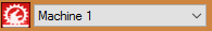
Select Machine:
1. The "Select Machine:" drop down menu is where users will choose their desired machine. To the right, the machine information will be shown.
Select Material:
2. The "Select Material:" drop down menu is where users will choose their desired material. To the right, the material information will be shown.
Stock Length:
3. The "Stock Length:" field is where users will enter the stock length of their material (in inches or millimeters based on the units of measurement specified in the "Options" menu).
Needed Lengths:
4. The "Needed Lengths:" section is where users will enter the values of their part lengths and quantities of each. These can be added by selecting the "Add" button below this section.
Add
5. Clicking the "Add" button will allow another line to be added to the "Needed Lengths:" section.
Remove
6. Clicking the "Remove" button will remove a line from the "Needed Lengths:" section.
Cancel
7. Clicking the "Cancel" button will close the simple nesting window and you will lose any progress made in this window.
OK
8. Clicking the "OK" button will send the "Needed Lengths:" to the "Dragon Nesting" interface where users will be able to view the lengths nested along their stock length of tubing. Editing can also be done there as well.
Edit Flat (Previously Dragon Design)
The
"Edit Flat/Dragon Design" interface is where users will do all the fine tuning of their part before fabrication. Here, you will be able to create holes and text among other things, manipulate the tube to reverse it, retrieve dimensions for distances on the tube, assign contours with marking, etching and cutting actions, placing the plasma lead in and so forth.

- The "Cancel"
 button is used to end a function that is currently in process or tied to your cursor. (Ex. If your text is tied to your cursor and you realize you made a typo, you can click the Cancel button and fix the typo before you place the text in the design.)
- The "Back"
 button will allow you to go back and re-do a step while operating a multiple step function
- Click the "Delete"
 button and then a feature in the design to erase it completely from the design.
- Click the "Free Select"
 button to enable the option to place an entity anywhere in the design. When Free Select is disabled, placement of entities in the design will be constrained to a point.
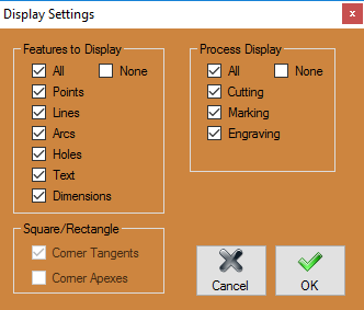
- Click the "Display"
 button to view and change settings for display.
- Click the "Paste"
 button after using the Copy tool in order to paste the desired part back into the design.
Action Tabs
Part Data
* The
"Part Data" tab shows current material, cut length, full bending instructions, options to change the bend order, add cut-off and personal dates and notes associated with the current part.
- The Machine
 that is applied to the part is shown in the upper left hand corner of the tab.
- The Cut Length
 for the part is shown in the upper right hand corner of the tab.
- The Material
 that is applied to the part is shown in the upper left hand corner of the tab under the Machine.
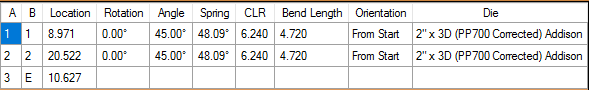
- The Bending Instructions section will show you the bend number, bend location, rotation, angle, spring angle, CLR and orientation for the current part.
- The "Bend Order"
 button will open the bending simulation and will allow the user to manipulate the part for bending only. Please see our Bend Order Tutorial in order to learn more.
- The "Reverse Tube"
 button will mirror all of the geometry of the part including copes, bend locations, text, holes, etc.
- The "Part ID:"
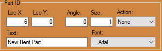 text field is where users can input a part identification name or number.
- The "Cut-Off Start:"
 and "Cut-Off End:"
  text fields are where users can input values to add cut-off to either end of the tubing.
- The "Date:"
 text field is where users can input a design date or fabrication date.
- The "Notes:"
 text field is where users can input any notes specific to the current part.
Create Geometry
Point
Cursor: Select the "Cursor" option and pick anywhere on the screen to click and place a point. The point will be placed at the exact location of your cursor and will not reference any other entities while being placed. The point will not be highlighted blue before placement.
Incremental: Select the "Incremental" function, provide X and Y coordinates into the "X:" and "Y:" value fields and select a reference point in the display area. X is the horizontal distance and Y is the vertical distance from the reference point. (Note: A negative (-) X value will place the point to the left of the reference point. A negative (-) Y value will place the point below the reference point.) The point will be highlighted in blue while the reference point is being chosen.
Angle: Select the "Angle" option under the point tab, enter the distance from the reference point in the "Distance" field and enter an angle in the "Angle" field. If the "Angle" field is set to 0°, the new point will be created directly to the right of the reference point. To place the new point, click on a point to use as a reference point. The point will be highlighted in blue while the reference point is being chosen.
Absolute: Select the "Absolute" option and enter X and Y coordinates into the "X:" and "Y:" fields and click the "Submit"  button to place the point. The reference point will always be (0,0) (or the origin that shows X and Y in the display area).
Intersection: Select the "Intersection" option followed by two intersecting lines in order to place a point at the intersection of the two lines.
Entity End: Select the "Entity End" option followed by an object or line in the display area to place an end point of that object. The point will be placed at the end that you click closest to. The point will be highlighted in blue before the object is chosen.
Entity Center: Select the "Entity Center" option followed by an object or line in the display area to place a center point on that object. The point will be placed directly in the center of the object highlighted. The point will be highlighted in blue and the point will be visible before the object is chosen. (Note: This option is not meant to find the center of self-created objects like flanges, but rather lines, arcs, text, tabs, slots along with holes).
Entity Mid-Point: Select the "Entity Mid-Point" option followed by an object or line in the display area to place a mid-point on that object. The point will be placed directly in the center of the section of the object highlighted. The point will be highlighted in blue and the point will be visible before the object is chosen. (Note: This option is not meant to find the center of self-created objects like flanges, but rather lines, arcs, text, tabs, slots along with holes).
Opposite Side: Select the "Opposite Side" option followed by a point to place a new point on the opposite side of the selected point.
button to place the point. The reference point will always be (0,0) (or the origin that shows X and Y in the display area).
Intersection: Select the "Intersection" option followed by two intersecting lines in order to place a point at the intersection of the two lines.
Entity End: Select the "Entity End" option followed by an object or line in the display area to place an end point of that object. The point will be placed at the end that you click closest to. The point will be highlighted in blue before the object is chosen.
Entity Center: Select the "Entity Center" option followed by an object or line in the display area to place a center point on that object. The point will be placed directly in the center of the object highlighted. The point will be highlighted in blue and the point will be visible before the object is chosen. (Note: This option is not meant to find the center of self-created objects like flanges, but rather lines, arcs, text, tabs, slots along with holes).
Entity Mid-Point: Select the "Entity Mid-Point" option followed by an object or line in the display area to place a mid-point on that object. The point will be placed directly in the center of the section of the object highlighted. The point will be highlighted in blue and the point will be visible before the object is chosen. (Note: This option is not meant to find the center of self-created objects like flanges, but rather lines, arcs, text, tabs, slots along with holes).
Opposite Side: Select the "Opposite Side" option followed by a point to place a new point on the opposite side of the selected point.
Line
Two Points: Select the "Two Points" option, click on a point in the display area and it will turn into a blue circle. Now click on a second point to create a line between the two points. Enable Continuous mode by clicking the "Continuous" checkbox. This will automatically start new lines with the first point set as the end of the last line. To stop drawing lines while in Continuous mode click "Cancel" in the "Activity" section.
Horizontal: Select the "Horizontal" option and set the length of the line by entering a value in the "Line Length:" field to create a horizontal line. Place the line by clicking a point in the display area. The mid-point of the line will be centered on the point you select.
Vertical: Select the "Vertical" option and set the length of the line by entering a value in the "Line Length:" field to create a vertical line. Place the line by clicking a point in the display area. The mid-point of the line will be centered on the point you select.
Horizontal and Vertical: Select the "Horizontal and Vertical" option to create two intersecting lines of equal length and set the line lengths using the "Line Length:" field. Click on a point to place the lines. Both lines will be placed with the intersection directly over the point you select.
Rectangle: Select the "Rectangle (Two Points)" option, click a point in the display area and creating a point will cause it to turn into a blue circle. A blue rectangle will be drawn between the selected point and the point nearest the cursor. Move the cursor near the intended second point and make sure the blue rectangle is correct. Click to create the rectangle.
Parallel: Select "Parallel" so you can either enter the distance between the parallel line and the reference line or use the "Through Point" feature. If a distance is entered and the Through Point checkbox is not selected, click a line to set it as the reference line. After picking the reference line, select which side the parallel line will be placed on by clicking on that side of the reference line. If the Through Point checkbox is selected you must first select a reference line, followed by a point that the parallel line will pass through.
Perpendicular: Select the "Perpendicular" option to create a line perpendicular to previously established line. Set the length of the perpendicular line using the "Line Length:" field. Then, click a line in the display area to set it as the reference line. The side you click on will determine the direction of the line. Click on any point to place the perpendicular line there.
Angle Absolute: Select the "Angle Absolute" option to create a line in the display area with a desired angle. First, enter the desired length in the "Line Length:" field and the desired angle in the "Angle:" field. Click on a point to place the Line there.
Angle Relative: Select the "Angle Relative" option and enter the length of the desired line in the "Line Length:" field and the relative angle in the "Angle:" field. Click on a line to use as a reference line and click on a point to use as a starting point for the new line. The angle of the line will be the sum of the angle of the reference line and the value entered in the Angle field.
Tangent through Point: Select the "Tangent through Point" option to create a line connected to an arc by clicking near the side of the arc that the line will be drawn to. Click on a point away from the arc to create the line.
Tangent Two Arcs: Select the "Tangent Two Arcs" option to add a line between two arcs by clicking near the side that the line will be drawn to. Select a second arc to create a line that attaches to the tangent of that arc.
Arc
Fillet: Select the "Fillet" option and input the desired radius of the filleted arc into the "Radius:" field. Click on the first line, which will turn blue. A blue arc will come off the first line and connect with whatever line is nearest to the cursor. Change the direction of the fillet by moving the cursor to the other side of the first line. Click to place the fillet. If the "Auto-Trim" checkbox is checked, any part of either line that extends past the fillet will be cut off.
Values: Select the "Values" option and input the "Radius:, Start Angle:, and End Angle:" of the arc into their respective fields. Click on a point to place the arc with its center directly over that point. Check the "Full Circle" checkbox to automatically set the start angle at "0" and the end angle at "360", creating a full circle.
Tangent - Three Lines: Select the "Tangent - Three Lines" option and set the start and end angle of the arc using the "Start Angle:" and "End Angle:" fields. Click on three lines within the part, in any order, to create an arc that uses those three lines as tangent lines.
Three Points: Select the "Three Points" option and pick three points that lie within the desired arc. The first and third points will be end-points. The second point will be on the arc and will define the radius of the arc. If the first and third points are the same point, a circle will be drawn between the first and second point.
Arc - Center and End Points: Select the "Arc - Center and End Points" option and click on the point that will lie in the center of the intended arc. Click on another point to create the first end point. A blue arc will be drawn from the first end point to the point on the arc closest to the cursor. Move the cursor until the second end point is in the desired location and click to place the arc.
Circle - Center and Edge Points: Select the "Circle - Center and Edge Points" option and click on a point to set it as the center point. A blue circle will be drawn with a radius equal to the distance to the point nearest to the cursor. Move the cursor to the desired point and click to place the circle.
Hole
Hole Shape
Round: Select Round, enter a diameter in the Diameter: field, and click on a point to place a round hole at that point.
Oval: Select Oval, enter a width and height in the Width: and Height: fields, and enter an angle for the hole in the Angle: field. Click on a point to place an oval hole at that point.
Square: Select Square, enter a width in the Width: field, and enter an angle for the hole in the Angle: field. If you want to automatically round the corners of the square, you can enter a value in the Corner Radius: field. Entering 0 in the Corner Radius field will result in square corners. Click on a point to place a square hole at that point.
Ellipse: Select Ellipse and enter a width and height in the Width: and Height: fields, and enter an angle for the hole in the Angle: field. Click on a point to place an elliptical hole at that point.
Rectangle: Select Rectangle and enter a width and height in the Width: and Height: fields. Enter an angle in the Angle: field and you can enter a value in the Corner Radius: field. Entering 0 in the Corner Radius field will result in square corners. Then, click on a point to place a rectangular hole at that location.
Hole Dimensions
Width: Enter the width of the hole in this text field.
Angle: Enter the angle the hole will rotate in this text field.
Corner Radius: Enter the size of the corner radius in this text field.
Height: Enter the height of the part in this text field.
Hole Location
Distance: Enter the distance from the origin that you would like to place a hole in this field.
Rotation: Enter the angle the hole will rotate around the tube in this text field.
Use Travel Distance: Check this box if you would like to use travel distance. This will make the rotation value a length around the circumference of the tube (inches or millimeters) rather than an angle of rotation (degrees).
Create Opposite Hole: Check this box if you would like to create an opposite hole.
Text
Create New Text/Text Properties
New: Click the "New" button and type the text that you want in the "Text:" value field.
Font Family: Select a font using the "Font Family:" drop down menu.
Font Size: Enter a size factor in the "Font Size:" value field.
Bold/Italic: Choose to make the text bold or italic by checking the "Bold" or "Italic" checkboxes.
Text Angle: Enter the angle of the intended text in the "Text Angle:" field.
Display: The text will be displayed in the screen below these sections before it is placed into the design.
Moving/Editing Text
Move: To move text, click the move button and click on a string of text in the display screen. Click on a point to place the text at the new location.
Edit: To edit an existing string of text, click on the Edit button and click on a previously placed piece of text. Make any changes to the Text Properties and Text Layout areas and click the Apply button.
Dimension
Create
Horizontal: Click the Horizontal button and click two points in the display window. A Dimension, along with dimension and extension lines, will appear and move with the cursor. Move the Dimension to the desired location using the cursor and click to place it.
Vertical: Click the Vertical button and click two points in the display window. A Dimension, along with dimension and extension lines, will appear and move with the cursor. Move the Dimension to the desired location using the cursor and click to place it.
Linear: Click the Linear button and click two points in the display window. A Dimension, along with dimension and extension lines, will appear and move with the cursor. Move the Dimension to the desired location using the cursor and click to place it.
Angle: Click the Angle button. Click the outside point of the first line. See the picture to the right for an example of outside and inside points. Your points can be endpoints of a line or individual points. Click the inside point of the first line. Now click the outside and inside points of the second line. The dimension, as well as a dimension arc and two extension lines, will be bound to the cursor. Move the cursor until the dimension is in the desired location and click to place it. To measure the reverse of the angle, click the "Flip Angle" checkbox.
Hole: Click the Hole button and click on a hole. The radius of the hole, along with an abbreviated version of the name of its shape, will be drawn and bound to the cursor. Move the cursor until the dimension is in the desired location and click to place it.
Edit
Move: Click on the Move button and click on a dimension. The dimension will now move with the mouse and can be repositioned. Click to place the dimension.
Edit Value: Click on Edit Value and click on a dimension. A window will pop up and ask for a new display value for the dimension. Enter a value and click on the "OK" button.
Edit Geometry
Features to Include
All: When the "All" checkbox is checked, all of the features will be included when selecting them in the display screen.
Points: When the "Points" checkbox is checked, the points will be included when selecting them in the display screen.
Lines: When the "Lines" checkbox is checked, the lines will be included when selecting them in the display screen.
Arcs: When the "Arcs" checkbox is checked, the arcs will be included when selecting them in the display screen.
Holes: When the "Holes" checkbox is checked, the holes will be included when selecting them in the display screen.
Text: When the "Text" checkbox is checked, the text will be included when selecting them in the display screen.
Dimensions: When the "Dimensions" checkbox is checked, the dimensions will be included when selecting them in the display screen.
Delete
Selection
Cursor Select: When the "Cursor Select" option is selected, the method which you select features to delete will be done simply by selecting them with your cursor.
Window: When the "Window" option is selected, you can select features to delete by creating a window around them using a simple two-click method.
Polygon: When the "Polygon" option is selected, you can select features to delete by creating a window around them using a multiple-click method. You can click as many times as you want in order to create an enclosure around the intended features.
Clean Up: The "Clean Up" button will remove any double lines or features that are irrelevant.
Move
Selection
Cursor Select: When the "Cursor Select" option is selected, the method which you select features to move will be done simply by selecting them with your cursor.
Window: When the "Window" option is selected, you can select features to move by creating a window around them using a simple two-click method. If "Window:" is selected a box will appear on the right side of the selection area where either "All In:" or "All Out:" may be selected. There is also an "Include Crossing:" checkbox. If All In is selected, the Window tool will allow the drawing of a window that will automatically select all items inside that window. If All Out is selected, the Window tool will automatically select all entities outside of the window. If Include Crossing is checked, items that cross the borders of the window will be included in the selection.
Polygon: When the "Polygon" option is selected, you can select features to move by creating a window around them using a multiple-click method. You can click as many times as you want in order to create an enclosure around the intended features. While using Polygon, make sure the All In/All Out and Include Crossing options are all set correctly. These options work exactly the same as when using Window.
Move/Copy Method
Incremental: Pick a Selection method from the Selection area. Select "Incremental:" and enter a "Horizontal:" and "Vertical:" distance to move the selection. Negative numbers may be used to move a selection left or down. Make sure the Selection and Move / Copy Method are already selected before clicking in the display window as the move will occur as soon as a selection is made. Select the entity or entities to be moved using the selection method that you chose. The Move will occur instantly upon selection.
Angle: Choose a Selection method and select "Angle:". In order to specify the direction of the move, an angle must be entered. Keep in mind that 0° is directly to the right. Enter the distance from the original location that the selection should travel. Use the selection method chosen earlier to select an entity or group of entities. The move will occur as soon as the selection is made.
Old - New: Choose a Selection method and select "Old - New:". Select an entity or multiple entities using the selection method you chose. Click on a point to set that point as the original base point. When a second point is clicked the selection will be moved. The original base point will be directly over the new base point.
Old - New with Direction: Choose a Selection method and select "Old - New with Direction:". Select the entity or entities using the selection method you chose. Choose an original base point and direction point. Now choose two new points to set as the new base point and direction point. The original base point will be positioned directly over the new base point, and the original direction point will be in line with the base points and the new direction point.
Mirror - Line: Choose a Selection method and select "Mirror - Line:". Select an entity or group of entities and click on a line. The entities will be mirrored across that line.
Mirror - Two Points: Choose a Selection method and select "Mirror - Two Points:". Make a selection using the chosen selection method. Choose two points. The entities will be mirrored across the line between the points, regardless of if a line exists there or not. The line between the points will not be drawn.
Rotation: Choose a selection method and select "Rotation:". Enter an angle in the Rotation Angle field. Select an entity or group of entities using the selection method you chose. Choose a point that the selection will rotate around. As soon as a point is selected, the rotation will be made.
Copy
Selection
Window: When the "Window" option is selected, you can select features to copy by creating a window around them using a simple two-click method. If "Window:" is selected a box will appear on the right side of the selection area where either "All In:" or "All Out:" may be selected. There is also an "Include Crossing:" checkbox. If All In is selected, the Window tool will allow the drawing of a window that will automatically select all items inside that window. If All Out is selected, the Window tool will automatically select all entities outside of the window. If Include Crossing is checked, items that cross the borders of the window will be included in the selection.
Polygon: When the "Polygon" option is selected, you can select features to copy by creating a window around them using a multiple-click method. You can click as many times as you want in order to create an enclosure around the intended features. While using Polygon, make sure the All In/All Out and Include Crossing options are all set correctly. These options work exactly the same as when using Window.
Trim
Trim Single: With "Trim Single:" selected, click on an entity that intersects another entity. Click on the side of the line that should be kept, rather than the side that is to be trimmed. The side of the entity that you click on will turn blue. Any part of that entity that is not blue will be trimmed off. Move the cursor close to the intersecting entity and make sure the correct section of the entity is blue. Remember that lines continue to infinity even if they are drawn with a finite length, so even if two entities don't touch they could still intersect. Click on the second entity to trim the first entity.
Trim Both: With "Trim Both:" selected, click on the side of the first entity that should be kept, rather than the side that will be trimmed. The first entity will turn blue. Anything in blue will be kept, while black sections of either entity will be trimmed off. Move the cursor near the second entity and make sure that the correct section of each entity is blue. Click to trim both entities.
Trim Continuous: With "Trim Continuous:" selected, click on an entity, making sure to click the side that should be kept, rather than the side that will be trimmed off. The entity will turn blue. Move the cursor near the next entity and make sure that every part of the first entity that should be kept is blue. Click to perform the first trim. Click the section of the next entity that should be kept. This will perform another trim. Continue making trims as long as is necessary. Click Cancel in the Activity area at any time to stop trimming.
Trim Double: With "Trim Double:" selected, click on the entity that will be trimmed. Make sure to click on the section that will be kept, rather than the section that will be trimmed. Click on the two entities that the first entity will be trimmed to.
Trim Divide: With "Trim Divide:" selected, click on the entity that will be trimmed. Click on two entities that intersect the first entity. The section of the first entity that lies between the second two entities will be removed.
Trim Gang: With "Trim Gang:" selected, click on the entity that others will be trimmed to. Now click on any intersecting entity to trim it to the first entity. The side of each entity that is clicked on is the side that will be kept.
Break Single: With "Break Single:" selected, click on an entity and click on an intersecting entity to break the first entity at the intersection point. Check the Create Point at Break box to create a point at the intersection of the two entities.
Break Both: With "Break Both:" selected, click on two entities in any order. Unlike Break Single, Break Both will break both entities. If the Create Point at Break checkbox is selected, a point will be created at the intersection of the entities.
Break Gang: With "Break Gang:" selected, click on the entity that will be used to break intersecting entities. Click on the intersecting entities one at a time to break them at the point of intersection with the first entity. If the Create Point at Break box is checked, a point will be created at each break.
Actions
The Actions tab contains buttons to help the user assign contours with either cutting, etching or marking. Here, you are able to assign the lead-in location and finely tune the actions that the Dragon machine will take while fabricating your part.
- Marking: Click the "Marking"
 button followed by a contour in the design to designate the action to that contour.
- Engrave: Click the "Engrave"
 button followed by a contour in the design to designate the action to that contour.
- Cutting: Click the "Cutting"
 button to access the cutting options. Options to select from include Start Cut, End Cut, Cutout, Peirce Hole, Polyline Cut and NonRotational Cut.
- Start Cut: Click the "Start Cut"
 option followed by the start cut of the tube to designate it.
- End Cut: Click the "End Cut"
 option followed by the end cut of the tube to designate it.
- Cutout: Click the "Cutout"
 option followed by a contour in the design to designate the cutting action to that contour.
- Pierce Hole: Click the "Pierce Hole"
 option followed by a location on a cut to indicate the location of the pierce (This will be a small hole created with only the kerf width of the plasma torch).
- Polyline Cut: Click the "Polyline Cut"
 option followed by a small section of geometry on a cut in order to convert all connected polylines to become a cut.
- NonRotational Cut: Click the "NonRotational Cut"
 option followed by a hole or a contour in the design to designate the nonrotational cutting action to that hole or contour.
- Cancel/Done: Click the "Cancel/Done"
 button to deactivate the cut function that has been selected.
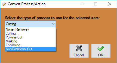
- Convert: Click the "Convert"
 button and click and drag a window over a contour or series of contours in order to change the action assigned to it/them. A window will appear with the options for "None (Remove), Cutting, Polyline Cut, Marking, Engraving and NonRotational Cut. Press the "OK" button to assign the selected action.
- Remove: Click the "Remove"
 button and click and drag a window over a contour or series of contours in order to remove it/them from the design.
- Edit Cuts: Click the "Edit Cuts"
 button and selection options will appear to allow you to edit a cutout, start cut, end cut or other. See how to use these functions in the Dragon Custom Design Tutorial or click on the Edit Cuts page to see how they all work individually.
- Move Lead: Click the "Move Lead"
 button and then the notch that represents the lead-in for a cut-assigned contour. Then, select the lead-in's new location. This is the plasma torch's piercing point.
- Move NRC: Click the "Move NRC"
 button followed by a nonrotational cut in the design. Click and drag the center location for the NRC in reference to the 3D wireframe image of the OD of the tube you're working on. This will not be able to exceed the top or bottom guidelines of the gray wireframe tube representation. See our Dragon Custom Design Tutorial to see how to use this function in action or select the Move NRC page for more detail.
Dragon Nesting
Action Tabs
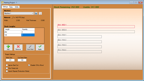
Settings
- Machine: The "Machine"
 section is where you select your desired machine.
- Material: The "Material"
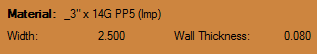 section is where the current material is shown. This includes diameter and wall thickness.
- Stock Lengths: The "Stock Lengths"
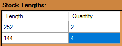 can be entered and shown here. This is the overall length of your stock pipe or tubing. Multiple lengths of tubing can be added to accommodate an entire project.
- Add: Click the "Add"
 button to add a new stock length of tubing to the list. Enter the length (in inches) in the Length value field and the quantity in the Quantity value field.
- Remove: Click the "Remove"
 button to remove the selected stock length from the list.
- Auto-Nest: Click the "Auto-Nest"
 button to automatically nest your parts.
- Apply: Click the "Apply"
 button when you have the stock lengths and quantities you are going to work with in the Stock Lengths list and they will appear in the display area to the right.
- Web Size: The "Web Size"
 can be entered and shown here. This is the default distance allowed between parts as they appear on the stock length of tubing in the design.
- Ignore Start Cut: Checking the "Ignore Start Cut"
 checkbox will cause the software to ignore the cut profile at the beginning of the stock tube.
- Disable OK to Move: Checking the "Disable OK to Move"
 checkbox will cause the Torch OK to Move reporting to be turned off. This is useful for dry running a project or other instances where the reporting is not needed.
- Run Partial Job: Checking the "Run Partial Job"
 checkbox will enable you to select individual stock pieces to process when transferring a project to the machine.
- Quick Repeat: Checking the "Quick Repeat"
 checkbox will cause the machine to repeat a project immediately upon completion.
Parts
- The "Parts" tab will show your parts and allow you to organize them according to order of fabrication. This tab will show the name, length and quantity of each part that has been imported into the current nesting project.
- Active Stick/Stick Selection: Click on the drop down menu displaying the current active stick
 and select a new stick to activate it. Parts added to the nesting project within the Parts tab will always be added to the active stick selected here. You may also use the "Left"
  and "Right"
  arrows to change sticks quickly.
- Part Sorting: Click on the drop down menu
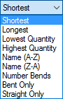 next to the "Active Stick/Stick Selection" box and you can choose how the parts in the nesting project will be organized.
- Auto Fill: Click the "Auto Fill"
 button on the master part and your selected stick will be filled with copies of the master part chosen.
- Flip Part: Clicking the "Flip"
 button will reverse all of the geometry of the highlighted part from the list above and create a new listed part. These will be marked Flipped in the part name.
- Remove Part: Clicking the "Remove"
 button will remove the highlighted part from the part list above.
- Quantity: Clicking the "Quantity"
 button will allow you to input the quantity you need for each part.
- Insert Part: Clicking the "Insert"
 button will allow the user to insert the highlighted part into the design at a location designated by the user. You may also double click the part in the list as a quick way to add the part to the stock tube.
- Re-Order: Clicking the "Re-Order"
 button will allow the user to select a length of tubing in the display screen and move it to a new location in the order.
- Move: Clicking the "Move"
 button and clicking an intended part in the display screen will allow the user to move the part along with every part behind it. Clicking once more will set the lengths of tubing where they are at that time.
- Rotate: Clicking the "Rotate"
 button and clicking an intended part in the display screen will allow the user to rotate the part itself around the diameter of the tubing. Clicking once more will set the length of tubing where it is at that time.
- Remove: Clicking the "Remove"
 button and clicking an intended part in the display screen will erase it from the nesting design.
- Rename: Clicking the "Rename"
 button will allow you to rename the current active stick.
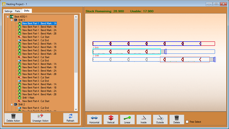
Shifts
- The Shifts tab will allow the user to assign the actions of the machine to each specific contour, profile and mark within the nesting project.
- Delete Action: Click the "Delete Action"
 button after a shift from the list above has been selected. It will be removed from the nesting project.
- Unassign Action: Click the "Unassign Action"
 button after a shift action from the list above has been selected. Then, contours inside the highlighted area will be excluded from the shift.
- Refresh: Click the "Refresh"
 button to undo all alterations made in the shifts order.
Dimensions
Horizontal: Click the "Horizontal"  button and click two points in the display window. A Dimension, along with dimension and extension lines, will appear and move with the cursor. Move the Dimension to the desired location using the cursor and click to place it.
Vertical: Click the "Vertical"  button and click two points in the display window. A Dimension, along with dimension and extension lines, will appear and move with the cursor. Move the Dimension to the desired location using the cursor and click to place it.
Linear: Click the "Linear"  button and click two points in the display window. A Dimension, along with dimension and extension lines, will appear and move with the cursor. Move the Dimension to the desired location using the cursor and click to place it.
Inside: Click the "Inside" angle  button to place an angle measure dimension at the inside of the intersection of two lines. First, select a line or reference point to represent the beginning of the dimension. Next, select the inside point of the line and/or the second reference line. Last, choose a location to place the dimension text.
Outside: Click the "Outside" angle  button to place an angle measure dimension at the outside of the intersection of two lines. First, select a line or reference point to represent the beginning of the dimension. Next, select the outside point of the line and/or the second reference line. Last, choose a location to place the dimension text.
Delete: Click on the "Delete"  button followed by a dimension in the design to delete it.
Free Select: Check the "Free Select"  check box to enable the option to place a dimension anywhere in the design. When Free Select is disabled, placement of dimensions in the design will be constrained to a point.
Run Project: When you are finished with your nesting project and are ready for fabrication, you can send all of this information to your machine by clicking on the "Run Project"  button at the top of the screen.


.png)
.png)

.png)

.png)
.png) button at the top of the screen. To learn more about this interface, scroll down to the "Custom Design" section of this Wiki.
button at the top of the screen. To learn more about this interface, scroll down to the "Custom Design" section of this Wiki..png) button.
button..png)
.png)
.png)


.png)
.png)
.png)


.png)
.png)
.png)
.png)
.png)
.png)


 button to place the point. The reference point will always be (0,0) (or the origin that shows X and Y in the display area).