Details
Bend-Tech 7x Wiki :: Assembly :: Details

In the details tab, a list of every material used in the assembly project will be listed along with the material's attributes, such as the name, width, amount used, and weight.
If weight per unit values have been given to the materials in the Tube/Pipe Library, the total weight of the assembly will be shown below the table.
Change Die or Material
Click the All Dies button ![]() to change all the dies used in the assembly to one specified die. After clicking the button, select a die from the menu and click the OK button to confirm the die change.
to change all the dies used in the assembly to one specified die. After clicking the button, select a die from the menu and click the OK button to confirm the die change.
Click the Match Die button ![]() to replace all bends using a certain die with an alternate die. In the menu, select the die that will be replaced and selected the die that will replace it. Click the OK button to confirm.
to replace all bends using a certain die with an alternate die. In the menu, select the die that will be replaced and selected the die that will replace it. Click the OK button to confirm.
Click the All Materials button ![]() to change all the materials used in the assembly to one specific material. After clicking the button, select a material from the menu and click the OK button to confirm the material change.
to change all the materials used in the assembly to one specific material. After clicking the button, select a material from the menu and click the OK button to confirm the material change.
Print Details
Click the Spreadsheet button ![]() to print out a page with an image of the 3D assembly model, the parts list, the chart shown in the Parts tab, and the material chart shown in the Details tab.
to print out a page with an image of the 3D assembly model, the parts list, the chart shown in the Parts tab, and the material chart shown in the Details tab.
Click the Setup Pack button ![]() to print out multiple setup sheets for the parts in the current assembly. In the Setup Pack menu, the printing options can be selected.
to print out multiple setup sheets for the parts in the current assembly. In the Setup Pack menu, the printing options can be selected.

- Select Features to Print: Select what kind of features will be included on the setup sheet.
- Select Printer: Choose the printer that the setup sheets will be printed from.
- Select Parts to Print: Choose which part setup sheets will be included in this printing. Click the Check All button to select all parts. Click the Check None button to un-check all parts.
Click the OK button to print the setup sheets.

Click the Full Scale button ![]() allows a full size, to scale, 2D version of the assembly design viewed from a specific direction to be printed to scale on multiple sheets. Each printed page will display one section of the full size assembly. When these pages are all combined, they will show the entire part design.
allows a full size, to scale, 2D version of the assembly design viewed from a specific direction to be printed to scale on multiple sheets. Each printed page will display one section of the full size assembly. When these pages are all combined, they will show the entire part design.
Adjust the settings explained below and click the Print button to print out a full scale part outline.
- Margins: The margins of each individual page can be set here in terms of inches.
- Default Orientation: The orientation of the pages can be adjusted here by choosing either portrait or landscape.
- Number of Pages: The width and height of the block of pages can be adjusted here. A preview of what the full group will be shown below. Each page is represented by a light blue outline.
- Line Width: The width of the line representing the part features can be adjusted here. Smaller values will result in thinner lines while larger numbers will result in thicker lines.
- Orientation: The angle that the part printout will be viewed from can be chosen here.
- Position... : To reposition the part outline on the pages, click the Position... button.
 The part outline will be attached to the cursor. Click to place the part in a new location. Keep in mind, if any of the part extends past the edge of the pages,
- Print Options:
- Select Printer: Choose which printer to print from here.
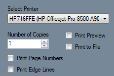

Number of Copies: The number of copies to print can be specified here.
Print Preview: Check this box to have a preview of the pages shown before it is printed.
Print to File: Check this box to save the pages as a Printer File (.prn).
Print Page Numbers: Check this box to print page numbers on each page.
Print Edge Lines: Check this box to include the margin lines on the pages.
- Preview: At the bottom of the window, a preview of the part outline and the pages will be shown.
- This preview can be adjusted by zooming, panning, and rotating. To zoom, use the scroll wheel on the mouse. Scroll up to zoom out and scroll down to zoom in. To pan/move the part preview, click and hold the scroll wheel or both mouse buttons and move the cursor around. The part preview will move with the cursor. To rotate, click and hold the right mouse button. Move the cursor around and the part will rotate with the cursor movements.
Assembly Tools
Click the Nesting button ![]() to
to

Click the Price button ![]() to view a chart containing the assembly's materials, quantity, and cost and time. These cost settings can be set up in the Tools Menu under Pricing Settings.
to view a chart containing the assembly's materials, quantity, and cost and time. These cost settings can be set up in the Tools Menu under Pricing Settings.
To add another column that will calculate the price for a specified amount of the part, enter a value into the Quantity First Field area or adjust the amount using the up and down arrows. Up to two extra columns can be added.
To add a second column, enter a value into the Quantity Second Field or adjust the amount using the up and down arrows.
To print the current view of the Price List chart, click the Print button. ![]()