Difference between revisions of "Header Design Tutorial"
| Line 3: | Line 3: | ||
Current Item: Header Design Tutorial | Current Item: Header Design Tutorial | ||
| + | |||
Contents[hide] | Contents[hide] | ||
| − | |||
1 Getting Started | 1 Getting Started | ||
2 Tutorial | 2 Tutorial | ||
| Line 21: | Line 21: | ||
2.13 Continuing On... | 2.13 Continuing On... | ||
| − | [edit] Getting Started | + | [edit] '''Getting Started''' |
This tutorial is designed to step you through creating an HD header assembly. As you step through this tutorial, procedures are designed on your knowledge of earlier procedures. Because of this, it is very important that you carefully go through this guide and understand everything along the way. | This tutorial is designed to step you through creating an HD header assembly. As you step through this tutorial, procedures are designed on your knowledge of earlier procedures. Because of this, it is very important that you carefully go through this guide and understand everything along the way. | ||
| Line 27: | Line 27: | ||
We would like to cover a few key items before starting the step-by-step instructions of the tutorial. It is very important you completely understand these items. | We would like to cover a few key items before starting the step-by-step instructions of the tutorial. It is very important you completely understand these items. | ||
| − | Assembly PickPoints: PickPoints are used for everything in the assembly. The assembly part of the software is largely run in full 3D, and because a computer screen in only 2D, there is an unlimited amount of depth when moving the cursor. PickPoints allow you to specify exact points in the 3D design. There are 2 types of PickPoints; Automatically created by the part(cyan) and user-defined points (green). In addition our 0,0,0 point is an automatic point and it resides in the center of the Tri-Star. The Tri-Star is our directional definition definition locator. | + | '''Assembly PickPoints''': PickPoints are used for everything in the assembly. The assembly part of the software is largely run in full 3D, and because a computer screen in only 2D, there is an unlimited amount of depth when moving the cursor. PickPoints allow you to specify exact points in the 3D design. There are 2 types of PickPoints; Automatically created by the part(cyan) and user-defined points (green). In addition our 0,0,0 point is an automatic point and it resides in the center of the Tri-Star. The Tri-Star is our directional definition definition locator. |
| − | Centerline & Apex: | + | '''Centerline & Apex:''' |
Centerline: In the assembly environment, we are working exclusively with the centerline of a part, as compared to the inside or outside. | Centerline: In the assembly environment, we are working exclusively with the centerline of a part, as compared to the inside or outside. | ||
| Line 35: | Line 35: | ||
Apex: The bend locations are created in assembly exclusively with the apex. Out definition of apex is the intersection of the straight tubes as if there wasn't a radius. | Apex: The bend locations are created in assembly exclusively with the apex. Out definition of apex is the intersection of the straight tubes as if there wasn't a radius. | ||
| − | Sense of Direction: It seems to work the best if users think as if they are standing behind the vehicle. This way left is always left and right is always right. Don't hesitate to take a minute and examine the tri-star to get your orientation. | + | '''Sense of Direction:''' It seems to work the best if users think as if they are standing behind the vehicle. This way left is always left and right is always right. Don't hesitate to take a minute and examine the tri-star to get your orientation. |
| − | [edit] Tutorial | + | [edit] '''Tutorial''' |
The following image shows the header we will be building in this tutorial. | The following image shows the header we will be building in this tutorial. | ||
| Line 50: | Line 50: | ||
[[File:AssemblyWindow.jpg]] | [[File:AssemblyWindow.jpg]] | ||
| − | [edit] Defining the PickPoints We Need to Know | + | [edit] '''Defining the PickPoints We Need to Know''' |
Before we get started creating an assembly in Bend-Tech HD, there are a few dimensions we must obtain. We need to find the locations of the following items: | Before we get started creating an assembly in Bend-Tech HD, there are a few dimensions we must obtain. We need to find the locations of the following items: | ||
| Line 85: | Line 85: | ||
6. The desired standoff length is 3.000 for each end. | 6. The desired standoff length is 3.000 for each end. | ||
| − | [edit] Creating PickPoints | + | [edit] '''Creating PickPoints''' |
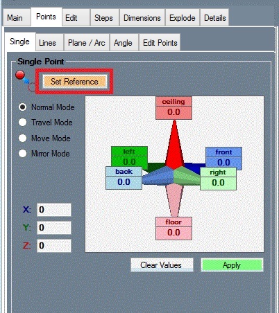
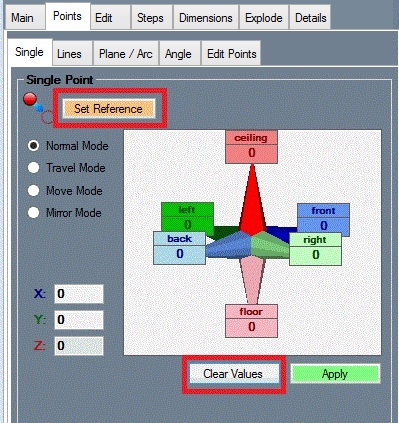
We will start by creating the PickPoints to represent the locations described above. PickPoints are used to located tubes at exact points and know bend locations. Click on the PickPoints tab. Within the PickPoints tab, multiple sub-tabs will be shown. Ensure that the Reference tab is selected then click the 'Set Reference' button. | We will start by creating the PickPoints to represent the locations described above. PickPoints are used to located tubes at exact points and know bend locations. Click on the PickPoints tab. Within the PickPoints tab, multiple sub-tabs will be shown. Ensure that the Reference tab is selected then click the 'Set Reference' button. | ||
| Line 190: | Line 190: | ||
[[File:TutorialSave.jpg]] [[File:Save.jpg]] | [[File:TutorialSave.jpg]] [[File:Save.jpg]] | ||
| − | [edit] Creating Tubes | + | [edit] '''Creating Tubes''' |
We have now created all the points we need to start creating tubes. Select the Headers tab. You will find several buttons and more tabs. | We have now created all the points we need to start creating tubes. Select the Headers tab. You will find several buttons and more tabs. | ||
| Line 257: | Line 257: | ||
[[File:ShadedTubes.jpg]] [[File:Finished1.jpg]] | [[File:ShadedTubes.jpg]] [[File:Finished1.jpg]] | ||
| − | [edit] Adding/Moving Bends | + | [edit] '''Adding/Moving Bends''' |
To start, we need to add a bend to the tubes. | To start, we need to add a bend to the tubes. | ||
| Line 332: | Line 332: | ||
[[File:CollisionBendApply.jpg]] | [[File:CollisionBendApply.jpg]] | ||
| − | [edit] Changing Tube Color | + | [edit] '''Changing Tube Color''' |
To change the color of the header tubes, go to the very top of the tabbed area and select the 'Parts' tab. | To change the color of the header tubes, go to the very top of the tabbed area and select the 'Parts' tab. | ||
| Line 343: | Line 343: | ||
| − | [edit] Tube Details | + | [edit] '''Tube Details''' |
Select the Create & Edit tab and then the Headers tab again. Within the Headers tab, select the Detail tab. this tab will display the details for a tube in the assembly. Select a single tube in the Tube list above by clicking on it. Once a tube is selected in this list it will be highlighted in yellow. A list will appear and display the following items: name, type, length, radius, angle, rotation, diameter, and material used. Each straight and bent or J-Bend section of the tube will have its own row in this list. You may need to use the scroll bar at the bottom of the list to see all the information. You can view a full size version of this chart by double clicking on it. | Select the Create & Edit tab and then the Headers tab again. Within the Headers tab, select the Detail tab. this tab will display the details for a tube in the assembly. Select a single tube in the Tube list above by clicking on it. Once a tube is selected in this list it will be highlighted in yellow. A list will appear and display the following items: name, type, length, radius, angle, rotation, diameter, and material used. Each straight and bent or J-Bend section of the tube will have its own row in this list. You may need to use the scroll bar at the bottom of the list to see all the information. You can view a full size version of this chart by double clicking on it. | ||
| Line 349: | Line 349: | ||
[[File:TubeDetails.jpg]] | [[File:TubeDetails.jpg]] | ||
[[File:tubedetails2.jpg]] | [[File:tubedetails2.jpg]] | ||
| − | [edit] J-Bends and Labels | + | [edit] '''J-Bends and Labels''' |
The default feature type in the software is no J-Bends, which means the software will display each arc and straight tube individually. the feature type for each tube can be changed under the Explode tab. | The default feature type in the software is no J-Bends, which means the software will display each arc and straight tube individually. the feature type for each tube can be changed under the Explode tab. | ||
| Line 362: | Line 362: | ||
You may also rotate and move the part around to a position that you like and then save the orientation using the 'Set Orientation' button. | You may also rotate and move the part around to a position that you like and then save the orientation using the 'Set Orientation' button. | ||
| − | [edit] Moving Labels | + | [edit] '''Moving Labels''' |
Make sure the 'Display Labels' box is checked. While this option is enabled, each section will be labeled in the part display frame to the right. | Make sure the 'Display Labels' box is checked. While this option is enabled, each section will be labeled in the part display frame to the right. | ||
| Line 374: | Line 374: | ||
Note: The J-Bend type, part orientation, and label locations are all saved with the part file when you save the assembly. | Note: The J-Bend type, part orientation, and label locations are all saved with the part file when you save the assembly. | ||
| − | [edit] Cutting J-Bends | + | [edit] '''Cutting J-Bends''' |
Bend-Tech HD has the ability to show you how to optimize and cut your J-Bends. Still within the Headers tab, select the Tools tab and you will find 2 command buttons among a couple other options. The 'J-Bend Library' button will open the J-Bend Library, which allows you to define the pre-bent J-Bends you will use with the software. Refer to the user Guide for more information on how to use the J-Bend Library. | Bend-Tech HD has the ability to show you how to optimize and cut your J-Bends. Still within the Headers tab, select the Tools tab and you will find 2 command buttons among a couple other options. The 'J-Bend Library' button will open the J-Bend Library, which allows you to define the pre-bent J-Bends you will use with the software. Refer to the user Guide for more information on how to use the J-Bend Library. | ||
| Line 402: | Line 402: | ||
Note: If you did not set a J-Bend type under the explode tab, you may find many parts in this list. Ensure that each tube in the assembly is not set to no J-Bends under the Explode tab. | Note: If you did not set a J-Bend type under the explode tab, you may find many parts in this list. Ensure that each tube in the assembly is not set to no J-Bends under the Explode tab. | ||
| − | [edit] Mirroring Parts | + | [edit] '''Mirroring Parts''' |
The mirror function allows you to mirror a single part in one of six directions, and to offset the part after it is mirrored. In the Headers tab, click the 'Mirror Tube' button and we will mirror both of our header tubes. Select the PickPoint on the first header tube and a menu box will appear in the top left corner (shown below). Select the Left option and enter 12 into the Distance field. Click the 'Apply' button to mirror the tube. | The mirror function allows you to mirror a single part in one of six directions, and to offset the part after it is mirrored. In the Headers tab, click the 'Mirror Tube' button and we will mirror both of our header tubes. Select the PickPoint on the first header tube and a menu box will appear in the top left corner (shown below). Select the Left option and enter 12 into the Distance field. Click the 'Apply' button to mirror the tube. | ||
| Line 426: | Line 426: | ||
[[File:FinishedMirror.jpg]] | [[File:FinishedMirror.jpg]] | ||
| − | [edit] Global Options | + | [edit] '''Global Options''' |
[[File:TutorialTools.jpg]] | [[File:TutorialTools.jpg]] | ||
Select the Tools menu at the top of the window in the main menu bar then select Options. This menu holds a series of tabs. Click on the 'Header Design' tab to access and adjust default settings for header designs. The values that are displayed are used as defaults during the operation of the software. Adjusting these values to what best works for you will save you time as you continue to use the software. | Select the Tools menu at the top of the window in the main menu bar then select Options. This menu holds a series of tabs. Click on the 'Header Design' tab to access and adjust default settings for header designs. The values that are displayed are used as defaults during the operation of the software. Adjusting these values to what best works for you will save you time as you continue to use the software. | ||
[[File:OptionsHeader.jpg]] | [[File:OptionsHeader.jpg]] | ||
| − | [edit] Printing | + | [edit] '''Printing''' |
Under the File menu you have the ability to select a printer and print a document. In many places, the software has Print command buttons available. these button typically represent a specific type of document to print. You will find an example of this on the Print tab under the Header tab. | Under the File menu you have the ability to select a printer and print a document. In many places, the software has Print command buttons available. these button typically represent a specific type of document to print. You will find an example of this on the Print tab under the Header tab. | ||
[[File:TutorialPrint.jpg]] | [[File:TutorialPrint.jpg]] | ||
| − | [edit] Continuing On... | + | [edit] '''Continuing On...''' |
We realize that this tutorial does not cover all areas of the software. However, we hope you found it to be helpful and that is has given you the tools to feel confident to explore more on your own. | We realize that this tutorial does not cover all areas of the software. However, we hope you found it to be helpful and that is has given you the tools to feel confident to explore more on your own. | ||
Revision as of 14:19, 16 July 2014
Jump to: navigation, search
Current Item: Header Design Tutorial
Contents[hide]
   1 Getting Started
   2 Tutorial
       2.1 Defining the PickPoints We Need to Know
       2.2 Creating PickPoints
       2.3 Creating Tubes
       2.4 Adding/Moving Bends
       2.5 Changing Tube Color
       2.6 Tube Details
       2.7 J-Bends and Labels
       2.8 Moving Labels
       2.9 Cutting J-Bends
       2.10 Mirroring Parts
       2.11 Global Options
       2.12 Printing
       2.13 Continuing On...
[edit] Getting Started
This tutorial is designed to step you through creating an HD header assembly. As you step through this tutorial, procedures are designed on your knowledge of earlier procedures. Because of this, it is very important that you carefully go through this guide and understand everything along the way.
We would like to cover a few key items before starting the step-by-step instructions of the tutorial. It is very important you completely understand these items.
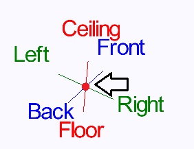
Assembly PickPoints: PickPoints are used for everything in the assembly. The assembly part of the software is largely run in full 3D, and because a computer screen in only 2D, there is an unlimited amount of depth when moving the cursor. PickPoints allow you to specify exact points in the 3D design. There are 2 types of PickPoints; Automatically created by the part(cyan) and user-defined points (green). In addition our 0,0,0 point is an automatic point and it resides in the center of the Tri-Star. The Tri-Star is our directional definition definition locator.
Centerline & Apex:
Centerline: In the assembly environment, we are working exclusively with the centerline of a part, as compared to the inside or outside.
Apex: The bend locations are created in assembly exclusively with the apex. Out definition of apex is the intersection of the straight tubes as if there wasn't a radius.
Sense of Direction: It seems to work the best if users think as if they are standing behind the vehicle. This way left is always left and right is always right. Don't hesitate to take a minute and examine the tri-star to get your orientation.
[edit] Tutorial
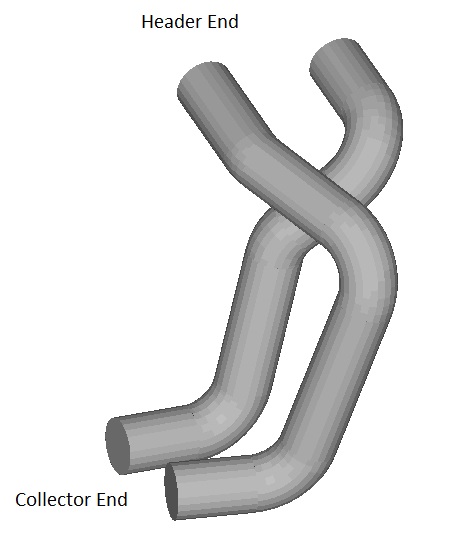
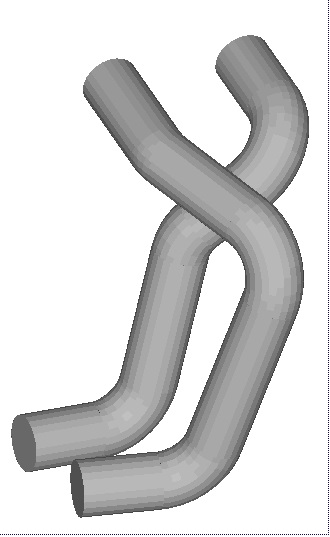
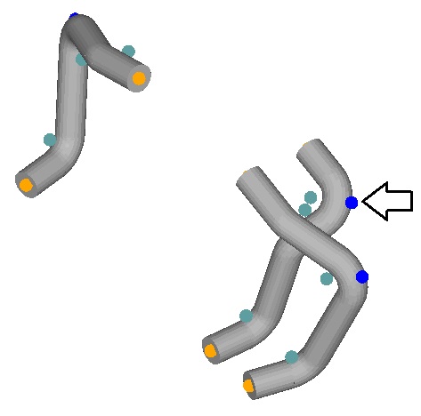
The following image shows the header we will be building in this tutorial.
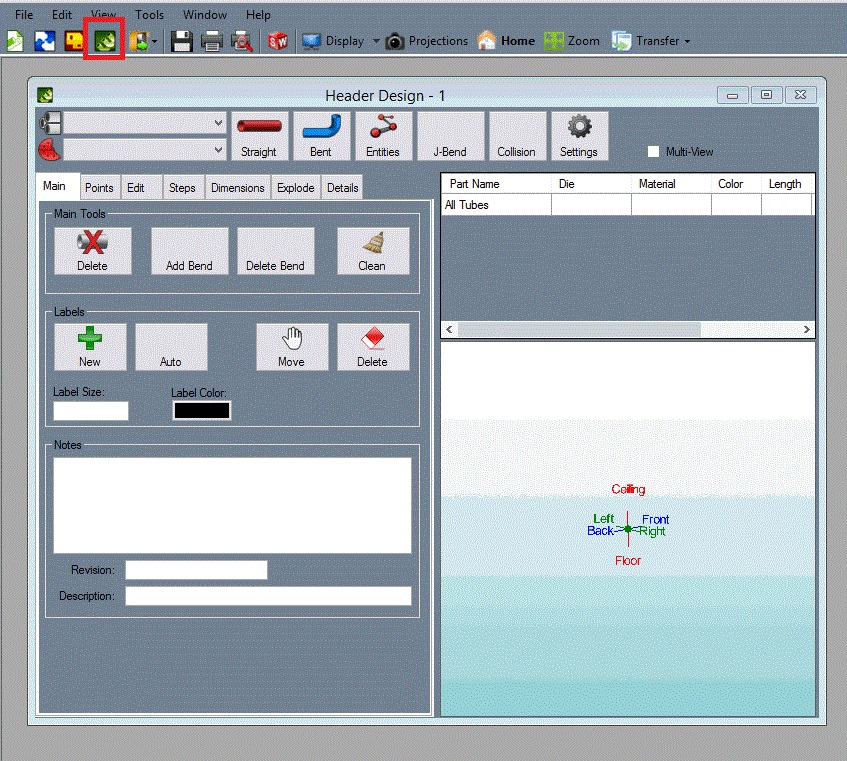
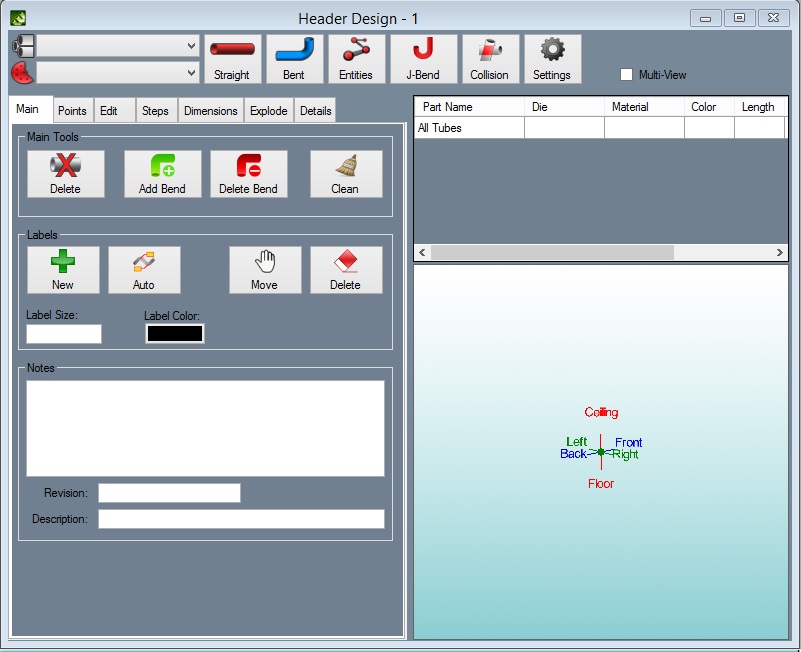
To begin, we must create a new assembly using the New Assembly button on the main toolbar, by selecting File --> New --> Assembly, or by selecting the 'Assembly' option in the New Design menu that appears when the software starts up. The new assembly will be displayed an can be broken down into two parts. The left side contains the features and value inputs while the right side is were we see and select the parts.
 [edit] Defining the PickPoints We Need to Know
Before we get started creating an assembly in Bend-Tech HD, there are a few dimensions we must obtain. We need to find the locations of the following items:
1. Distance between header ports
2. Angle projecting away from the heads
3. Location of the collector in relationship to one of the heads
4. Relationship between collector ports
5. Angle projecting away from the collector back down the tube
6. Desired standoff lengths on both the head and collector tubes
Note: We will be using the terms header and collector very loosely. When referring to each, we are simply trying to describe the end of the tube we are referring to.
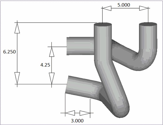
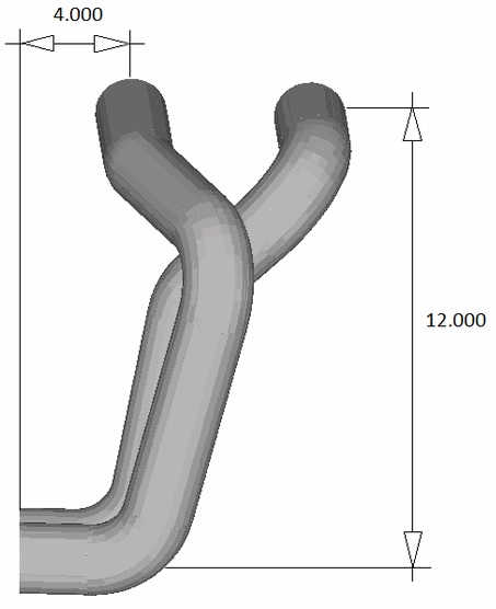
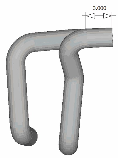
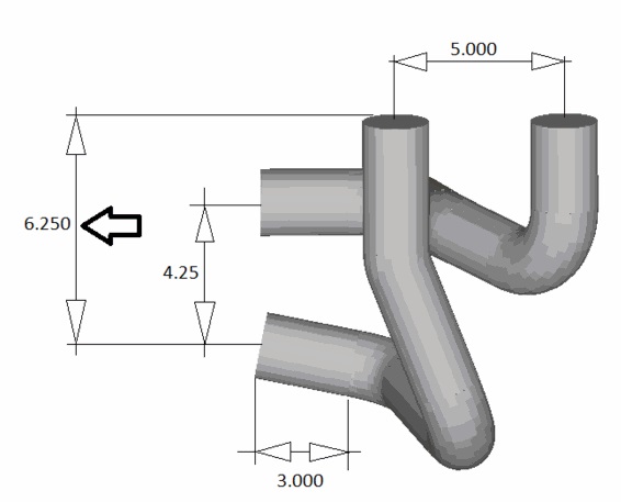
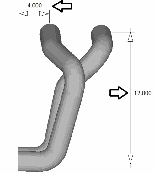
You will find in our diagrams that all of the needed locations have been defined:
1. Distance between header ports is 5.000.
2. Angle projecting away from the heads is 15 degrees.
3. The location of the collector in relationship to one of the heads is: 4.000 to the back, 12.000 towards the floor, and 6.250 towards the right.
4. The location of each collector port is 4.250.
5. The angle projecting away from the collector is 0 degrees (straight towards the front).
6. The desired standoff length is 3.000 for each end. [edit] Creating PickPoints
We will start by creating the PickPoints to represent the locations described above. PickPoints are used to located tubes at exact points and know bend locations. Click on the PickPoints tab. Within the PickPoints tab, multiple sub-tabs will be shown. Ensure that the Reference tab is selected then click the 'Set Reference' button.
We will use the Tri-Star point as our first reference point for adding new PickPoints. It may be hard to see, but there is a green PickPoint at the center of the Tri-star. Select this point. Once selected, it should turn red.
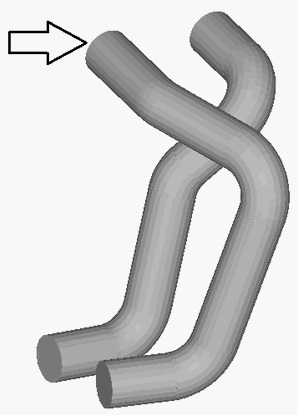
This PickPoint will be the header end of our first tube, as shown below. We will refer to this tube as our first header tube. The other tube will be referred to as the second header tube.
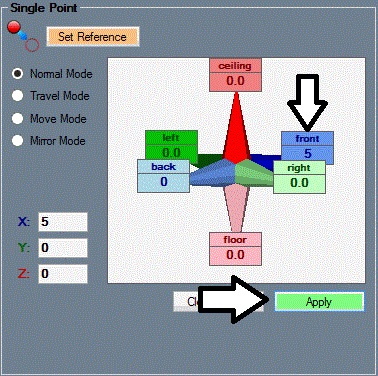
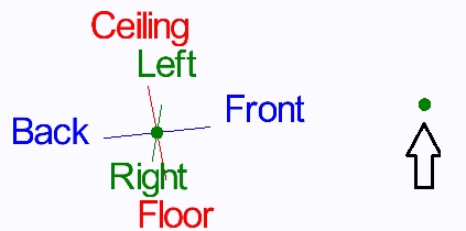
The first PickPoint we create will be the header location for the second header tube. You will find the distance between header ports is 5.000. The direction from the point we selected above to the second header port is towards the front.
Enter 5 into the Front field on the Reference tab. (You do not need the decimal and three zeros.)
As you enter values into these fields you will notice a green outlined, white PickPoint appear.This PickPoint represents the location of the new PickPoint based on the values that have been entered. This PickPoint is NOT part of the assembly until you click the 'Apply' button.
Click the 'Apply' button. The green outlined white PickPoint will turn green. Your assembly should look similar to the following image.
We now have our 2 header port locations, one at the Tri-Star and one 5 inches to the front. Now we will put in the PickPoints that are the start location of the first bends. These points can be referred to as the tangent points or the ends of the stand-off.
We will be using the Angle PickPoint method to locate these points. Select the Angle tab.
Click the 'Set Reference' button on this tab and click on the Tri-star PickPoint, which will turn red once selected.
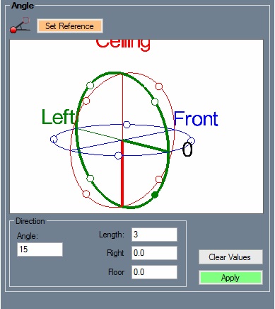
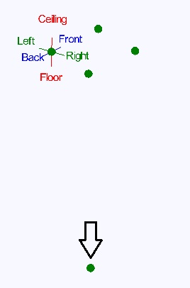
We are now going to select the direction for this point. The first thing to do is to select which direction we will be moving. This is a combination of selecting a quadrant from the Tri-Globe and entering in the angle. The Tri-Globe consists of 3 interlaced circles, each circle representing a plane in space broken into four quadrants. Each quadrant is defined by a small circle. You select the quadrant you want by selecting the appropriate circle.
In our case, we want to go towards the right and towards the floor at 15 degrees. the large green dial represents this direction. Select the quadrant as sown in the image here.
Change the Angle field to 15 and the Length field to 3.
If the screen looks like the image below, click 'Apply'.
We have now completed the first tangent point for our first header tube. Now we will locate the tangent point for the second header tube.
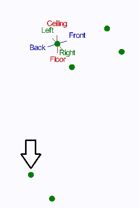
Select the header port location point of the second tube to set it as the reference point (shown below). Note: You should still be in the Angle tab with the same values entered from the last point.
The new point should appear in purple. Click the 'Apply' button to create this new point.
The four PickPoints are done for the header side of both tubes. We will now locate the four PickPoints on the collector side.
Select the 'Reference' tab and then click the 'Set Reference' button. Click on the Tri-Star PickPoint to set it as the reference point and it should turn red.
Note: The values we entered before into the Front field may still be present. It is always a good idea to use the 'Clear Values' button to clear all direction fields before entering new values.
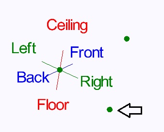
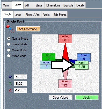
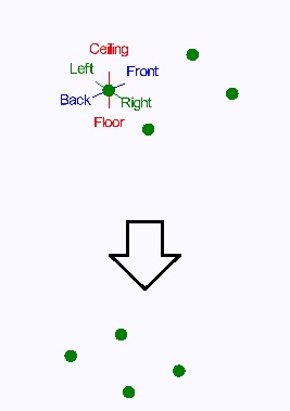
According to the dimensions for our part, the collector end of the first tube is Back 4 inches, Right 6.25 inches, and Floor 12 inches - from the header end of the first tube. Enter these values into the appropriate fields (shown below).
Click the 'Apply' button. A new PickPoint should be located as shown below.
Click the 'Clear Values' button to clear all fields. Select the PickPoint that we just created to set it as the reference point.
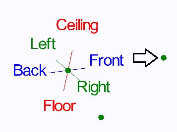
The distance for the second tube's collector end is 4.25 inches to the left of the first tube's collector end. Enter 4.25 into the Left field and the new PickPoint should be displayed to the left of the last point. Select the 'Apply' button to create this point.
Now it's time to locate the tangent points for the collector end of the tubes. Click the 'Clear Values' button to clear the direction fields.
Select the PickPoint we just created to set it as the reference point (shown above). Enter 3 into the Front field and select the 'Apply' button.
Select the PickPoint that is the collector end of our first tube to set it as the reference point and then click the 'Apply button.
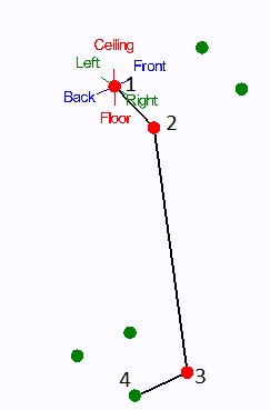
You should now have the four points for the collector end of our tubes as shown below.
This is a good time to save our work. Select the File menu at the top of the screen and click the Save option. Enter a name for this assembly and select the 'Save' button. You have now saved this assembly to a file with the name you entered.
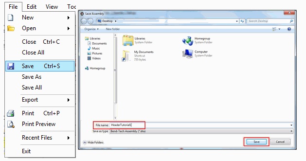 File:Save.jpg
[edit] Creating Tubes
We have now created all the points we need to start creating tubes. Select the Headers tab. You will find several buttons and more tabs.
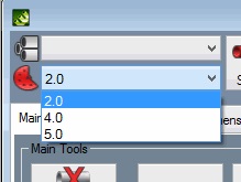
We start by selecting a default die and material. Within the Headers tab, select the Misc tab and click the drop down menu arrow for the Default Die/CLR option. Select a die from the the list that appears. For this tutorial, we will be using a 2.0 CLR die.
Note: If the die is not available in the list, it needs to be added to the Die Library. You cannot simply type in a CLR into the list. Refer to the User guide for information on adding dies to the Die Library.
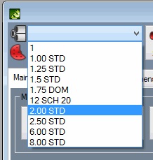
We will perform similar steps to select our material. Stay in the Misc tab and click the drop down menu arrow for the Default Material option. Select a material from the list that appears. For this tutorial, we will be using a material with a 2.0 outside diameter. Select 2.0 from the list.
Note: If the material is not available in the list, it needs to be added to the Tube/Pipe Library. You cannot simply type a material into the list. Refer to the User Guide for information on how to add a material to the Tube/Pipe Library.
We are going to be creating one tube at a time. We will start out by creating the first header tube.
Select the 'New Tube' button at the top of the Headers tab. You will now notice that the PickPoints we created earlier will now be displayed in the part display window to the right.
To create a tube, we select four PickPoints in order starting from one end.
1. Header Location
2. First tangent after Header
3. Tangent before collector
4. Collector Location
Note: The order in which you select the PickPoints is extremely important!!!
For the first tube (below), select these four points:
1. The header end - This is the Tri-Star point
2. The first tangent
3. The tangent before the collector
4. The collector end
After you have selected the four points, the software will add the radii and create the part.
Repeat this process for the second tube. Select the 'New Tube' button and select the PickPoints as shown below.
After you have selected the four points for the second tube, the software will add the radii and create the part. We are now done creating the two header tubes.
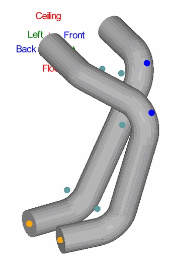
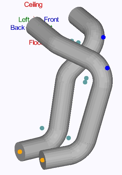
You may select the Display Mode menu at the top of the window and choose the 'Shaded' option to see a shaded display of the tubes. you can also zoom, pan, or rotate the display of the tubes using the mouse controls. To zoom, use the mouse scroll wheel. Scroll up to zoom , scroll down to zoom in. Pan/move the display by either clicking and holding the scroll wheel button or both mouse buttons and moving the cursor around. Rotate the display by clicking and holding the right mouse button and moving the cursor around.
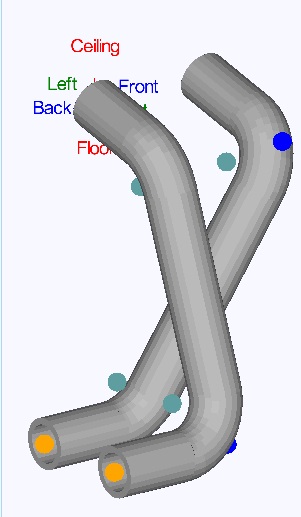
Currently, our header tubes look like the picture below on the left. We will manipulate these tubes so that they look like the picture below on the right.
To start, we need to add a bend to the tubes.
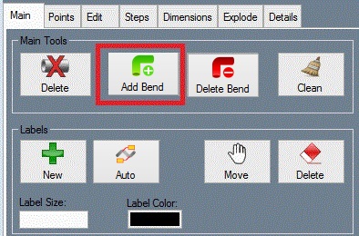
Select the 'Add Bend' button at the top of the Headers tab. The display will show pickpoints only at the locations where a bend can be added. Please not that bends cannot be added between the end of the tube and the first bend (on either end).
Select the PickPoint on the first tube and a bend will be added to the tube. The bend may be hard to notice, as it has a very small angle.
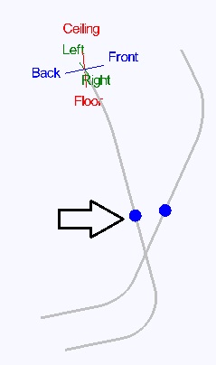
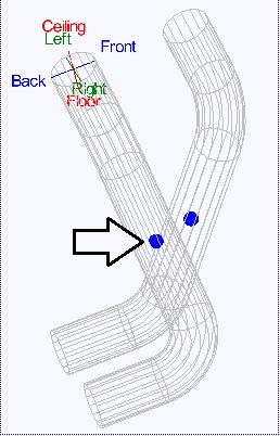 Note:
Note:
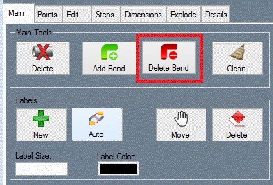 If you accidentally selected the wrong tube for the bend, you may use the the 'Undo' option under Edit in the main menu bar or the 'Remove Bend' button at the top of the Headers tab to delete the wrongly placed bend.
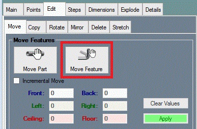
Now we will move the bend we just created to the correct location. Select the 'Move Bend' button.
Note: The first and last bends on any tube cannot be moved and are not available to be selected.
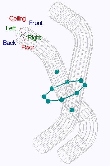
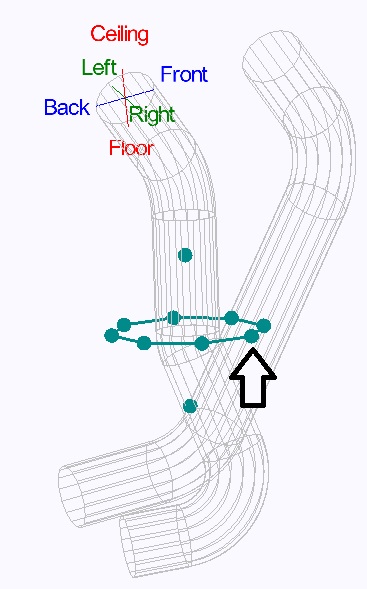
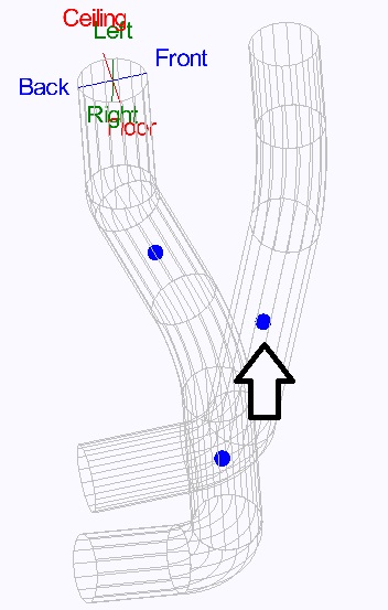
After selecting the 'Move Bend' button, click on the bend we just added to the first header tube. A ring and a front and back set of teal PickPoints will appear around the chosen bend. This directional ring is used to allow you to move in 3D space by using the mouse (which moves in 2D).
Each point on the ring represents a direction to push/pull the bend.
First, select the point that is shown in the image below. To select the point, you must click and release the mouse as you would with a PickPoint. Once the point has been selected, move the cursor around to adjust the location of the bend. The bend will only move in the direction that was chosen.
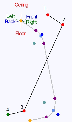
Continue selecting points and moving the bend until it looks similar to the image below. You will need to move the bend up (using the PickPoint just above the ring) at some point to get it a bit closer to the top of the tube.
Next, we will add a bend to the second tube. Click the 'Add Bend' button and select the PickPoint on the second header tube.
Note: You will now see the first header tube has two locations to add a bend, one on either end of the bend we added above.
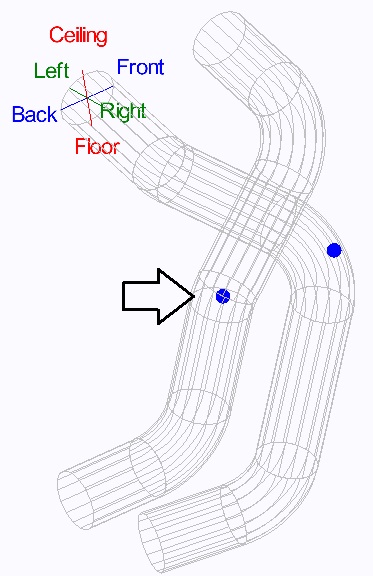
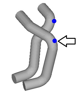
After selecting the second header tube to add a new bend, we will move the new bend. Click the 'Move Bend' button and click on the PickPoint on bend of the second header tube shown below.
Select the directional PickPoint as shown below on the left. Keep selecting direction points and moving the bend so that it looks similar to the image below on the right.
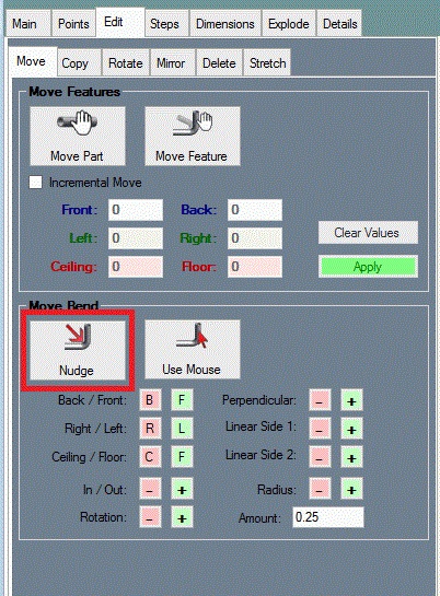
As you may notice, the Move Bend command is for large, inaccurate movements. For fine movements of bends, HD has the Nudge function, which allows for small movements in absolute directions. In the Headers tab, select the 'Nudge' tab. You will find several '+' and '-' buttons. The display will also show a PickPoint for every bend that can be moved. Nudge allows the first and last bend on each tube to be slid in and out only.
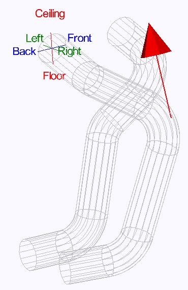
Click the 'Select Bend' button and select a PickPoint on one of the bends. Now place your cursor over the '+' and '-' buttons and you will see a direction arrow as shown below. This arrow will show the direction each button will move the bend.
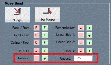
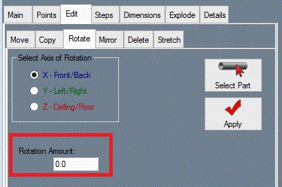
Each press of any of these buttons will move and/or rotate the bend by the amounts specified in the Push Amount and or Rotate Amount fields. You many also hold down the button to continue moving the bend in the selected direction.
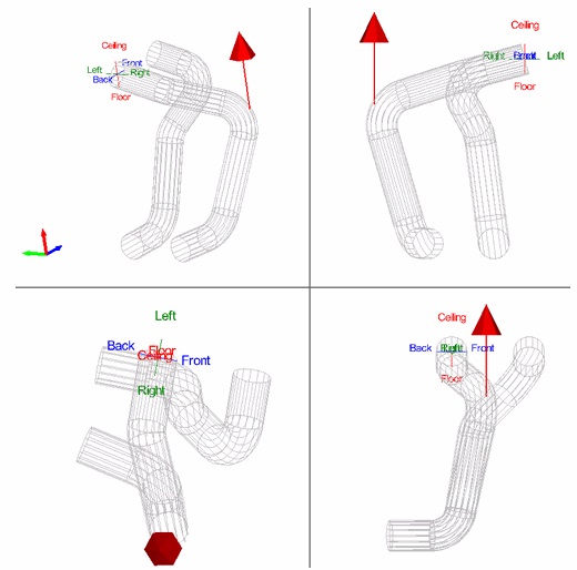
While the box next to Multi-View is checked, the display screen will be separated into four sections (shown below), each displaying a different angle view of the header tubes. This can make it easier to see where the bend is being moved.
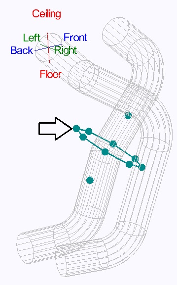
After moving a bend you must select the 'Apply' button to apply the movement. Use the 'Select Bend' command button if you need to select a different bend to move. You can also rotate the picture around to check for interference between the tubes or by using the 'Collision Check' button. If a collision between tubes occurs, you will find points down the middle of the tube where the collision is found.
To change the color of the header tubes, go to the very top of the tabbed area and select the 'Parts' tab.
In this tab you will see a list of all tubes in the assembly. You can change the color of any tube by selecting the colored cell for the tube in the Color column. Once you select a cell, you will be prompted to select a color for the tube. Select the color you desire and select the 'OK' button. The chart and part display will be updated with the color you selected.
[edit] Tube Details
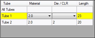
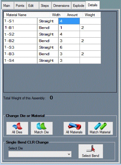
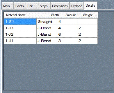
Select the Create & Edit tab and then the Headers tab again. Within the Headers tab, select the Detail tab. this tab will display the details for a tube in the assembly. Select a single tube in the Tube list above by clicking on it. Once a tube is selected in this list it will be highlighted in yellow. A list will appear and display the following items: name, type, length, radius, angle, rotation, diameter, and material used. Each straight and bent or J-Bend section of the tube will have its own row in this list. You may need to use the scroll bar at the bottom of the list to see all the information. You can view a full size version of this chart by double clicking on it.
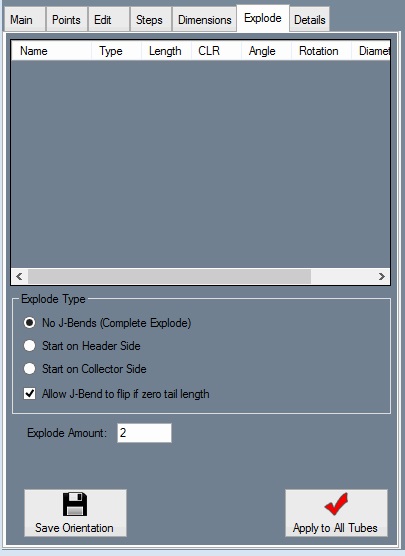
The default feature type in the software is no J-Bends, which means the software will display each arc and straight tube individually. the feature type for each tube can be changed under the Explode tab.
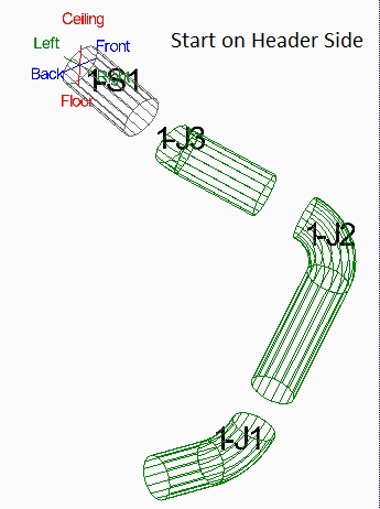
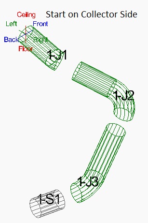
Within the Headers tab, select the Explode tab. Ensure that Tube 1 is selected from the list above. If it isn't, select it by clicking on Tube 1 in the list. Once selected, it will be highlighted in yellow. Select the Start on Header Side option.
You will find that the tube coming out of the header is a straight tube and not a J-Bend. If you select Start on Collector Side, you will find the tube coming out of the header IS a J-Bend and the last tube is a straight tube. See the images below for an example of how this looks.
You may also rotate and move the part around to a position that you like and then save the orientation using the 'Set Orientation' button. [edit] Moving Labels
Make sure the 'Display Labels' box is checked. While this option is enabled, each section will be labeled in the part display frame to the right.
If you select the 'Move Labels' button, you will be allowed to move each label anywhere on the screen by selecting the PickPoint representing the label.
Still within the Headers tab, you may now select the Detail tab and review the updated information with J-Bends enabled.
Note: The J-Bend type, part orientation, and label locations are all saved with the part file when you save the assembly.
[edit] Cutting J-Bends
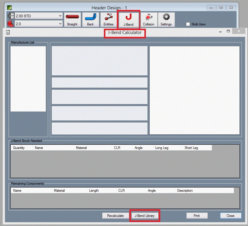
Bend-Tech HD has the ability to show you how to optimize and cut your J-Bends. Still within the Headers tab, select the Tools tab and you will find 2 command buttons among a couple other options. The 'J-Bend Library' button will open the J-Bend Library, which allows you to define the pre-bent J-Bends you will use with the software. Refer to the user Guide for more information on how to use the J-Bend Library.
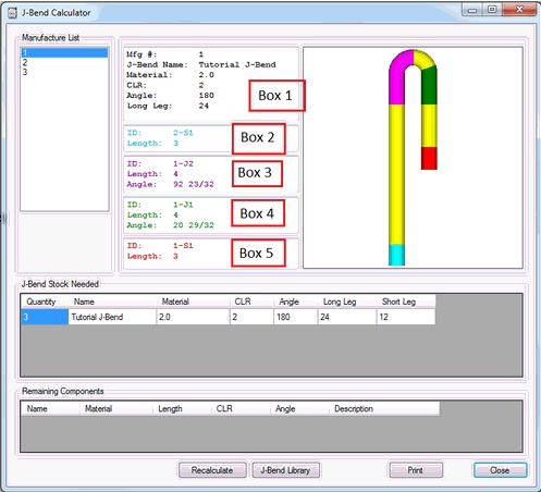
The 'J-Bend Calculator' button will calculate and display recommended methods for cutting your J-Bends to manufacture the header tubes you have designed. Click the 'J-Bend Calculator' button.
A new window will be displayed with a multicolored J-Bend and information in several boxes. This information defines how the J-Bend should be cut:
Box 1: The description of the material stick (J-bend) needed.
Box 2: The straight tube on the long side.
Box 3: The J-Bend on the long side. This description is both the bend and straight length for this section.
Box 4: The J-Bend on the short side. This description is both the bend and straight length for this section.
Box 5: The straight tube on the short side.
Note: Some material sticks (J-Bends) may not consist of all four sections being used. the yellow sections display on the J-bend are scrap.
The software may not be able to find a suitable solution for some components in your header tubes. If any components cannot be manufactured from the available J-bends in your J-Bend Library, a list will be display on the bottom of the J-Bend calculator.
Note: If you did not set a J-Bend type under the explode tab, you may find many parts in this list. Ensure that each tube in the assembly is not set to no J-Bends under the Explode tab. [edit] Mirroring Parts
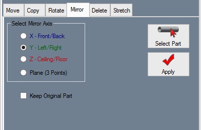
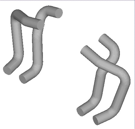
The mirror function allows you to mirror a single part in one of six directions, and to offset the part after it is mirrored. In the Headers tab, click the 'Mirror Tube' button and we will mirror both of our header tubes. Select the PickPoint on the first header tube and a menu box will appear in the top left corner (shown below). Select the Left option and enter 12 into the Distance field. Click the 'Apply' button to mirror the tube.
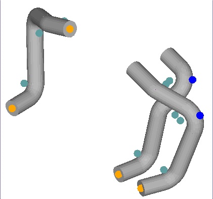
The tubes should now look like the image below.
Now we need to mirror the second tube. Click the 'Mirror Tube' button again. Click on the second header tube PickPoint and the mirror menu box will appear again (shown below). Select Left and enter 12 into the Distance field. Click the 'Apply' button to mirror the tube.
If both tubes have been successfully mirrored, the tubes should look like the image below.
 [edit] Global Options
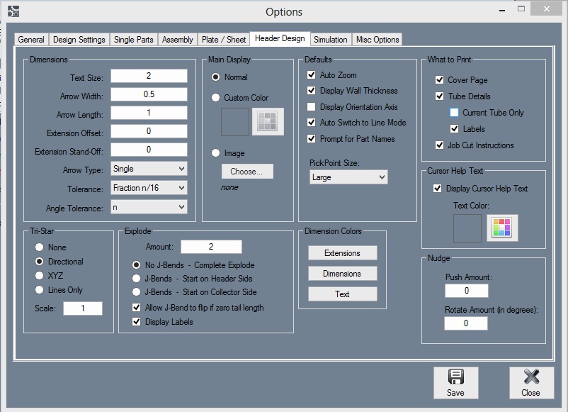
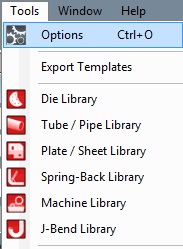 Select the Tools menu at the top of the window in the main menu bar then select Options. This menu holds a series of tabs. Click on the 'Header Design' tab to access and adjust default settings for header designs. The values that are displayed are used as defaults during the operation of the software. Adjusting these values to what best works for you will save you time as you continue to use the software.
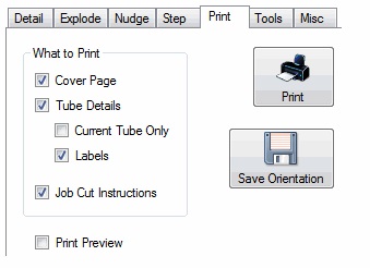
Under the File menu you have the ability to select a printer and print a document. In many places, the software has Print command buttons available. these button typically represent a specific type of document to print. You will find an example of this on the Print tab under the Header tab.
We realize that this tutorial does not cover all areas of the software. However, we hope you found it to be helpful and that is has given you the tools to feel confident to explore more on your own.
