Difference between revisions of "Plate Tutorial"
| Line 313: | Line 313: | ||
*Select the "'''Part'''" tab followed by the "'''Assembly'''" sub-tab. | *Select the "'''Part'''" tab followed by the "'''Assembly'''" sub-tab. | ||
*Now, select three points defining the base point and direction of the part. Also, assign a depth to these points. We will define the points on the bottom of the material, so we will leave the Depth at 0.0. | *Now, select three points defining the base point and direction of the part. Also, assign a depth to these points. We will define the points on the bottom of the material, so we will leave the Depth at 0.0. | ||
| − | *Select the "'''Set'''" button in the Base Point area. Select the lower-left corner, the lower-right corner, and then the upper-left corner of the base flange (in that order). The "'''Send'''" button should now be available. | + | *Select the "'''Set'''" button in the Base Point area. Select the lower-left corner, the lower-right corner, and then the upper-left corner of the base flange (in that order). The "'''Send'''" [[File:send_assembly1.png]] button should now be available. |
| − | *Make sure you are selecting the corners of the base flange and not part of the bend zones. You must take care when selecting the points. Once you have properly selected the three points, select the "'''Send'''" button. | + | *Make sure you are selecting the corners of the base flange and not part of the bend zones. You must take care when selecting the points. Once you have properly selected the three points, select the "'''Send'''" [[File:send_assembly1.png]] button. |
The image here shows the points to pick. | The image here shows the points to pick. | ||
[[File:W126.JPG]] | [[File:W126.JPG]] | ||
| − | *Now, select "'''New Assembly'''" from the drop-down list. | + | *Now, select "'''New Assembly'''" from the drop-down list. [[File:SM_new_assembly1.png|right]] |
*You will be prompted to give the part a name. Name the part however you wish and select the "'''OK'''" button. The part will be opened in the Assembly. You should see the part in the "'''Master Part List'''" and a preview of it to the right. | *You will be prompted to give the part a name. Name the part however you wish and select the "'''OK'''" button. The part will be opened in the Assembly. You should see the part in the "'''Master Part List'''" and a preview of it to the right. | ||
To continue, create a new part. | To continue, create a new part. | ||
Revision as of 11:24, 17 November 2014
This tutorial is designed to walk you through the steps in creating a part using the sheet metal module.
Sheet Metal/Plate Design
- This tutorial will begin by showing how to create a specified piece of bent sheet metal designed with "PickPoints".
- "If you're not familiar with this interface, it is suggested that you visit the Sheet Metal Module page for better understanding of the basics."
Things To Know
- "This tutorial is designed to walk the user through creating a sheet metal/plate design. As you go through this tutorial, later procedures will assume that you understand all earlier procedures. Because of this, it is very important that you carefully step through this guide, understanding everything along the way and following all steps in order."
- "A few key items need to be addressed before starting the step-by-step instructions of this tutorial. It is very important for Bend-Tech users to completely understand these items:"
- 1) PickPoints
- PICKPOINTS ARE USED FOR EVERYTHING. The Sheet Metal part of the software is largely run in full 3D. Because a computer screen is only 2D, there is an unlimited amount of depth behind and in front of the cursor. A PickPoint is a point in 3D space that can be used for creating, editing, and placing parts in handrail design. PickPoints can be placed in a 2D environment by having their depth manually entered in the appropriate value fields.
- There are 2 types of PickPoints; Those automatically created by the part by default (various colors) and user-defined points (green). In addition, the initial (0,0,0) point is an automatic point that resides at the center of the Tri-Star. The Tri-Star is our directional definition locator.
- 2) Center Line & Apex
-
- Center Line: In the Sheet Metal design environment we are working primarily with the "center-line" of a part, as compared to the inside or outside.
- Apex: Most bend locations are created in Sheet Metal design with the "Apex". Our definition of apex is the intersection of the straight tubes as if there wasn’t a radius.
- This is demonstrated in the picture below.

- 3) Locational Orientation
-
- Designing seems to work the best if users imagine as if they are standing at a 45 degree angle to the desired creation. This way left is left and right is right. Take a minute and examine the Tri-Star (under the PickPoints] tab) to get your orientation.
Start Up
1) Start by double clicking the "Bend-Tech 7x" icon to start up the program.![]()
2) Select the "Plate" icon ![]() in the Task Menu under the "Create New" section to open the Sheet Metal/Plate interface, Or... select the Plate button on the main toolbar, OR... select File → New → Plate.
The window that opens should be labeled [Plate - 1].
in the Task Menu under the "Create New" section to open the Sheet Metal/Plate interface, Or... select the Plate button on the main toolbar, OR... select File → New → Plate.
The window that opens should be labeled [Plate - 1].
3) For the purposes of this tutorial, click the "Maximize" button ![]() at the top right of the plate design window.
at the top right of the plate design window.
4) Also, for the purposes of this tutorial, zoom out significantly by spinning the wheel on your mouse so that the Tri-star is about the size of a pea in the lower left corner of the display area.
The Assembly Interface
- The Assembly Interface is designed to allow you to assemble multiple parts together. Parts can also be made in the assembly, however it is usually quicker and more accurate (although not necessarily easier) to use one of the part interfaces to create parts.
Free Select
- Free Select can be used to allow the user to click anywhere on the screen as if there was a point. Whenever Free Select is on, the display window is dimmed slightly. It is very difficult to place points with precision using Free Select mode, so make sure you take it off whenever you are trying to do something where precision matters.
CAD vs Sheet Metal
- The Part Interface is basically divided into 2 areas, a simple CAD interface and sheet metal functions. The CAD functions allow you to create a part using points, lines, arcs, and other features for the part, much like other CAD software. These functions include trimming/extending lines, using tangent and intersection points, and placing dimensions. The sheet metal portion of the software allows you to convert features into a flange and add flanges together with bends.
Bending Radius
- When creating a bent part and setting up a material in the Plate Material Library, it is important to understand that the bending radius is the INSIDE radius of the bend. While some areas of the software may use the centerline dimensions, the bending radius of each bend on a sheet metal part is referring to the Inside Radius.
- The following image shows the part we will be building in this tutorial.

Creating The Base Flange
- To begin, the new plate interface will be displayed and can be broken down into two parts: The left side contains the features and value inputs, while the right side is where we see and select the features of the part. The large window on the right side of the screen is referred to as the Display Area in this tutorial as in most others.


- The first step to most any part is to create some points defining the part’s base flange. All features of a part can be created under the "Create" tab (except for bends).
- Select the "Create" tab.
![]()
- The "Point" sub-tab will be displayed, showing the different methods you can use to create a point.
- Notice that the part already has a point created at the (0, 0) coordinate. This point is the first point in our part.
As seen below, our first part is 8 inches wide, so start by creating the base flange that wide.
- Select the "Incremental" point option.

- Type a value of 8 in the X value field as shown here.
- As you move the cursor over the part, you will notice a point 8 inches to the right.
- Now, select the base point to create the new point with the offset.
- Select the base point (origin) of the part and the software will create the new point 8 inches in the X-direction.


- Next, we will create a point 6 inches above this new point.
- Type 0 in the X field and 6 in the Y field. This will create a point 6 inches above our cursor.
- Select the point created in the last step to create the third point of the flange.
- The next point we create will be 6 inches above the base (origin) point. We already have this offset in the fields so we can simply select the origin point to create the fourth point.


- The four points now define the outer edge of our base flange. Connect these points with four lines.
- Select the "Create" tab (if it is not already selected).
- Select the "Line" tab.
- Select the "2 Points" option.
- Click the "Continuous" checkbox next to the "Two Points" option.
- Select the upper-left point for the first point of the line. Select the origin point as the second point of the line.

You will now have a line created, connecting the 2 points you selected.

- Click the top right point in the display area, then the bottom right point and finally the bottom left point making a rectangle like in the picture below.
The base part is complete.

Defining the Base Flange
- Now that we've completed our 8 inch by 6 inch base flange, we must define the flange.
- Select the "Part" tab. In the "Definition" sub-tab, click the "Library" button. The Plate / Sheet Library will open.

- There are two Add New buttons. Click the left one and type “.25 Inch” in the Material Name field.
- Type ".25" in the thickness field (the field with the arrow pointing towards it in the picture below). Make sure Inches is selected in the Units area and click the Apply button.
- (Note) Make sure to "Save" this to the "Material List" in order to perform the next steps.

- Click on ".25 Inch" in the Material List. Click the right "Add New" button.
- Type ".5" in the "Inside Bending Radius" value field and click the "OK" button.
- Type "40" for the K-Factor and click the "OK" button. Click the Apply button, then the Close button to close the Plate / Sheet library.

- Go to the "Part" tab.
- Select ".25 Inch" in the "Material" drop down menu. Click the "Define Flange" button.
- Click anywhere inside the box that you made in the display area. You should see the "Flanges List" button turn green, indicating that a flange has been defined successfully.


- Go to the "Bends" sub-tab within the "Part" tab.
- In the "Bend Properties" section, change the "Flange Initial Height" to "3". Make sure "0.5" is selected in the "Inside Bend Radius" value field and "Up" is selected in the "Direction" section.

- Change the "Parent" and "Child Bend Location" to "Outside Apex".

- Select the "New" button. Click the line on the left side of the box you made. You will be prompted to name the flange. By default it will be named “Flange 2” which is good enough.
- Select the "OK" button. You should now see two new areas created on the part. The first area is the bend zone, an area between each flange that extends from the start of the bend to the end of the bend. The second area that was created is the second flange, which is built according to the Flange Initial Height we specified ( 3 inches in this case ). Your screen should now look like the picture below.

(Note) The two flanges and bend zone will overlap, as we have selected Outside Apex for both sides of the bend. The bend zone extends from the tangent of each side. If we have selected tangent for both sides, the bend zone would not overlap.

- Select the "New" button. Click the line on the right side of the box in the display area.
- You will be prompted to name the flange, but “Flange 3” is good enough.
- Select the "OK" button.
Your part should now look like the picture below.

- On the "Toolbar", click the arrow next to the "Display Mode" button. Select "3D Shaded". The part will now be displayed in full 3D.
Click and hold the right mouse button on the part to rotate the display or click and hold both mouse buttons to pan. Use the scroll wheel to zoom in and out.
- Go back to the "Display Mode" menu on the "Toolbar" and select "Design".


- Now, to define the two new flanges, go to the "Definition" sub-tab within the "Part" tab. Select on the "List" button in the "Flanges" area.
- Double Click on "Flange 2".

- Select the "Define Flange" button and click on the line on the right side of "Flange 2". See the picture below to make sure you are selecting the correct line.

- Use the List menu in the Flanges area to select Flange 3. Click the "Define Flange" button and click on the line that is on the left side of "Flange 3".

Internal Features
- Now that the main structure of the part has been created, we will begin creating the internal features of each flange. In order to create a feature on a flange, that flange must be the active flange. We will begin with the base flange.
- Use the "Flange List" to select the Base Flange item.
- The first flange you've created should now be active (the other flanges should be gray).
- Referring to the part dimensions, create a square hole and a custom cutout in this flange. First, create the square hole, however, we must create a point to place the hole with. Go to the Create tab and make sure you are in the Point sub-tab.
Select Incremental. Enter 2 in the X field and 3 in the Y field. Click the bottom left point of the base flange, which is also the location of the XY axis.


- Go to the "Hole" sub-tab within the "Create" tab. Select "Square" in the "Hole Shape" area. Type "1" in the "Width" value field, "0" in the "Angle" value field, and "0" in the "Corner Radius" value field.
- Select the point that you just made in the display area to place the hole there.


- The upper-left corner of the cutout is 2 inches to the right of the center of our square hole. Try using the Angle method of creating a point for the first one.
- Go to the "Point" sub-tab within the "Create" tab.
- Select the "Angle" option and enter Angle: 0, Distance: 2.
- Since we created the point for the square hole, we can use that as the reference point for the new point. Select the point at the center of the square hole to create a new point 2 inches to the right.
- Our next point is located 1 inch down from this new point. Change the values in the Angle fields to Angle: 270, Distance: 1.
- Select the last point we created to create the new point. You should now have 2 points created for the cutout.
- The next point is located 2 inches to the right of the last point we created. Change the values in the Angle fields to Angle: 0, Distance: 2. Select the last point we created to create the new point.
- The last point is located 2 inches above the last point we created. Change the values in the Angle fields to Angle: 90, Distance 2. Select the last point we created to create the new point.
- The four points of our cutout have been created . We can now connect these points with lines.

- Go to the "Line" sub-tab within the "Create" tab.
- Select "Two Points" and check the "Continuous" checkbox. Select the upper-left point of our cutout. You will notice that the point turns into a blue circle. *Select the point directly below this point to create the first line. Since Continuous mode is enabled, you may continue selecting points to create lines.
- Select the bottom right point of the cutout, followed by the top right point, and click the top left point to finish the shape. See the picture below.

- Click the top left point to finish the shape. See the picture below.
- Once you create the last line, a line will still be attached to your cursor, as Continuous mode is still enabled. Select the "Cancel" button on the top of the screen to cancel creating lines. Go to the "Arc" tab. Select "Fillet", change the Radius to "0.5" and check the "Auto-Trim" checkbox.

- Click on the right line of the cutout, followed by the bottom line. This will create a fillet at the intersection of the two lines.

- The cutout should now look like the picture below. We must now define both of the holes on the flange. To do so, all we need to do is define the flange like normal. The holes will automatically be defined along with the flange.

- Go to the "Definition" tab within the "Part" tab.
- Select the "Define Flange" button and click the bottom line of the Base Flange.
 The base flange of our part is now complete. Now, move on to the left side flange. This flange has a single circular hole on it.
- Select the "Flange List" button and select "Flange 2". Close the Flange List by selecting the "List button" again.
The flange on the left of our part will now be the active flange. To create the circular hole, we will first need to create the center point.
- Select the "Create" tab.
- Select the "Point" sub-tab.
- Select the "Entity Center" option.
The hole is centered on the flange, so we will use the Entity Center feature to locate a point on the center on the flange’s edge line.
- Select the left-most vertical line of the flange. A point will be created at the center of this line.
Now, create a point "1.5 inches" from this edge.
- Select the "Incremental" point method and type in the values shown here:

- Select the new point we just created. A new point will be created to the right of it. Now that we have created the point for the hole, we can create the hole. We will use an arc for the hole.
- Select the "Arc" tab.
- Select the "Values" option and enable the "Full Circle" option. Type in a radius of "0.5" in the "Radius" field. Since we are creating a complete circle, the start and end angle fields are not available.

- Select the point we created in the center of the flange to create the circle. Once again, we will need to re-define this flange in order to update the part.
- Select the "Part" tab.
- Select the "Definition" tab.
- Select the "Define Flange" button and then select the left-most vertical line of the flange. The flange and the circle hole will be defined.
Now, create the holes in the final flange. Click the "Select" button next to the Flange area. We will use this method to select the flange we wish to work on.
- Select the far-right line on the right flange. This flange will become the active flange; we can now create the features.

- Select the "Create" tab followed by the "Point" tab.
- Select the "Incremental" option and enter the values shown here: We will be creating a point 1.5 inches from the edge of the part and 1 inch in. Note the negative sign in the X field.

- To create the point, select the bottom right corner of the flange, this will place the point as shown in the picture below.

- Select the "Hole" tab.
- Select the Rectangle shape and enter "0.5" for Width, "0.1" for Corner Radius, "1'" for Length and "0" in the Angle field.
- Select the point that we just created to place a hole there.
We now have the first hole of this flange. To create the remaining holes, we will use "Move/Copy".
- Select the "Edit" tab and select the "Move" sub-tab. Ensure "Cursor Select" is selected under "Selection".
- Uncheck the "All" box under "Features to Include". Next, check the "Holes" box to allow us to select only holes.
- Select the "Move - Incremental" option and enter "1" in the Vertical value field.
- Also, enable the "Duplicate" option, otherwise we will simply move the hole. We want to copy the hole and create 4 copies; this will give us the 5 holes needed on this flange. The holes will be evenly spaced 1 inch apart vertically.
- Check the "Duplicate" checkbox and enter "4" in the "Number of Copies" field.
- Select the rectangle hole we created earlier. Four copies of the hole will be created instantly. Your screen should look like the picture below.

- Go to the "Definition" tab inside the "Part" tab. Select the "Define Flange" button and click the line on the far right side of Flange 3. In the "Display Mode" drop down menu in the toolbar, select "3D Shaded". Your part should look like the picture below.
- Use the Display Mode menu to switch back to Design view when you are finished viewing the part.

PickPoints
We will now create some PickPoints on the part for use in the assembly. As stated before, PickPoints are crucial to the placement of parts in the assembly. All creation and editing in the assembly is done with Pickpoints. We will create some PickPoints on the part to allow us to assemble our parts.
- Be sure that the right flange is the active flange. If not, select it from the "Flanges List" before moving forward.
- Select the "Create" tab followed by the "Misc" sub-tab. Inside the Misc tab, go to the PickPoint tab.
- Create a Pickpoint on the far edge of the part, on the bottom of the material. Ensure that the Depth is set to 0.0 and then select the lower-right corner of the right flange. The Pickpoint will be created.
- Next, create two Pickpoints on the left flange of the part. Select the Flange List and select the left flange. Select the List button again to close the list.
- Select the lower-left corner of this flange to create the first Pickpoint. Next, select the upper-left corner to create the second Pickpoint.
- We have now created the three Pickpoints we will later use in the assembly.
(Note) The flange you are working on must be the active flange.
Send to Assembly
We will now send the completed part to an assembly. This will allow us to create the second part and assemble them together.
- Select the "Part" tab followed by the "Assembly" sub-tab.
- Now, select three points defining the base point and direction of the part. Also, assign a depth to these points. We will define the points on the bottom of the material, so we will leave the Depth at 0.0.
- Select the "Set" button in the Base Point area. Select the lower-left corner, the lower-right corner, and then the upper-left corner of the base flange (in that order). The "Send"
 button should now be available.
 - Make sure you are selecting the corners of the base flange and not part of the bend zones. You must take care when selecting the points. Once you have properly selected the three points, select the "Send" button.

The image here shows the points to pick.

- Now, select "New Assembly" from the drop-down list.
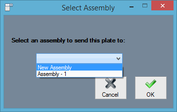
- You will be prompted to give the part a name. Name the part however you wish and select the "OK" button. The part will be opened in the Assembly. You should see the part in the "Master Part List" and a preview of it to the right.

To continue, create a new part.
- Open a new Part Interface by clicking on the "New Plate"
 icon in the main toolbar.
![]()
- Select the "Create" tab followed by the "Point" button.
- Select the "Incremental" option and input values as shown here:

- Select the origin point to create the new point, 1 inch above and 1 inch to the right.
- Select the "Absolute" option and input the values shown here:

- Select the "Submit" button to place the point 9 inches to the right and 1 inch above the origin point.
The two points we just created will be used for positioning the part when we send it to the assembly. Now we must create a third point for the part itself.
- Select the "Incremental" option again and input these values:

- Select the origin point and the point will be created. We can now create the lines for this part.
- Select the "Line" tab.
- Select the "Rectangle" (2 Points) option.
- We are going to create a rectangle by specifying two opposite corners. Select the origin point as the first point of the rectangle. Select the point that is farthest to the top right. We now have created the rectangle part we need. However, we must first define it before moving forward.
- Select the "Part" tab.
- Select the "Definition" tab.
- Select the same material we used for the previous part from the Material drop-down list. Select the "Define Flange" button.
- Click one of the four lines of the rectangle to define the part.
The part should now be defined. We can send this part to the assembly to assemble it with our other part we created.
- Select the "Assembly" tab.
- Select the "Assembly" drop-down list and select the assembly we already have opened.
- Now we must select the three anchor points for the part. We will use the two points we created earlier. Select the first point, the second point, and the upper-left corner of the part (in that order). Leave the Depth at 0 (zero) for all three of the points.

- The Send button should now be available. Select the "Send" button. Leave the parts name as “Plate 2” and click the "OK" button in the Plate Name window. The part will then be opened in the assembly. We should now have two parts available in the assembly.
Now that we have both parts created, we must create a few base pickpoints in the assembly. The pickpoints will be used to position our first part.
- Select the "PickPoints" Tab.
- Select the "Reference" Tab.
- Select the "Set Reference" button.
- Create a pickpoint by using the "Incremental" method in the Plate Interface, but select the reference point first, then enter the values for where the point is to be located. The one point created for us already lies at the center of the origin or tri-star. This point is the (0, 0, 0) coordinate.
- Select this point. It should turn red.
Now type in the values for the new point. Type "8" in the Front value field. Select the "Apply" button followed by the "Clear Values" button. Type "6" in the Left value field and select the "Apply" button.

- Select the "Main" Tab.
- Select “Plate 1” (the 3-flange part).
- Select the "Paste Part" button.
The part is now ready to be pasted into the assembly. To add the part, we must select three anchor points in the design area. These points will coincide with the three points we used when transferring the part to the assembly.
- Select the origin point as the base point for the part. The point should turn red.
- Select the first point we created (in the to front direction) as the second anchor point. The point should turn red.
- Select the second point we created (in the to left direction) as the final anchor point. The part will now be displayed in the design area.
You should notice the PickPoints we created with the part are displayed with the part. We will use these points to attach the next part.
- Select “Plate 2” from the "Master Parts List" (part with no bends).
- Select the "Paste Part" button. Once again we need to select three points in the design area to paste the part. Select the three Pickpoints that we created with the first part as shown below in the specified order.

Once you select the third point, the part will be added to the assembly. Your assembly should now look similar to the picture below.

- Select the "Projection" button at the top of the design area.
- Select the "Right" button.

The view will re-orientate itself so hat you are looking at the assembly from the right side. Your assembly should look similar to the picture below.

Dimensions: We will now add several dimensions to the assembly to verify the overall dimensions of the parts.
- Select the "Dimension" tab.

- Select the "Horizontal" button.

- Create a dimension measuring the overall width of the first part. Select the two Pickpoints shown below-left, you will then need to select a location to create the dimension. *Select the two points shown below-right to create a dimension measuring the width of the part.


Now, add a dimension to measure the height of the first part created.
- Select the "Vertical" button.

- Select the bottom and top point of the right side of the flange to create the vertical dimension shown above.
We have now concluded this tutorial. You may experiment more with this part if you wish. For further information, please use the Help menu in the software or visit the rest of the wiki pages here.