Difference between revisions of "Plate"
| Line 62: | Line 62: | ||
===How-To=== | ===How-To=== | ||
*'''Refresh: '''Refreshes the Flat Layout. If the Flat Layout is refreshed, any changes that you have made to it using the Tools tab will be lost. | *'''Refresh: '''Refreshes the Flat Layout. If the Flat Layout is refreshed, any changes that you have made to it using the Tools tab will be lost. | ||
| + | |||
| + | |||
*'''Toggle: '''Switches between the Design View and the Flat Layout. | *'''Toggle: '''Switches between the Design View and the Flat Layout. | ||
| + | |||
| + | |||
*'''Export: '''Exports the Flat Layout as a .DXF file. | *'''Export: '''Exports the Flat Layout as a .DXF file. | ||
| + | |||
| + | |||
*'''Line Type: '''Select a line type in the [[Tool Bar (Plate)|Tool Bar]] and click the Line Type button in the Tools tab. Select a line to change its type. For information on selection, see the [[Selection (Edit)|Selection]] and [[Features to Include (Edit)|Features to Include]] pages. | *'''Line Type: '''Select a line type in the [[Tool Bar (Plate)|Tool Bar]] and click the Line Type button in the Tools tab. Select a line to change its type. For information on selection, see the [[Selection (Edit)|Selection]] and [[Features to Include (Edit)|Features to Include]] pages. | ||
| + | |||
| + | |||
*'''Color: '''Select a color in the [[Tool Bar (Plate)|Tool Bar]]. Click the Color button in the Tools tab and use a [[Selection (Edit)|Selection]] feature of your choosing. If desired, you may also use the [[Features to Include (Edit)|Features to Include]] function. | *'''Color: '''Select a color in the [[Tool Bar (Plate)|Tool Bar]]. Click the Color button in the Tools tab and use a [[Selection (Edit)|Selection]] feature of your choosing. If desired, you may also use the [[Features to Include (Edit)|Features to Include]] function. | ||
| + | |||
| + | |||
*'''Clean Up: '''Deletes any duplicate features or zero-length features. | *'''Clean Up: '''Deletes any duplicate features or zero-length features. | ||
| + | |||
| + | |||
*'''Flange Intersection: '''Click on the Flange Intersection button and click on two intersecting flanges. | *'''Flange Intersection: '''Click on the Flange Intersection button and click on two intersecting flanges. | ||
| − | + | ||
| + | ==Settings== | ||
| + | '''Description''' | ||
| + | [[File:Settings.jpg|right]] | ||
| + | The Settings tab contains various options that can be used to customize interface. | ||
| + | |||
| + | ===Settings=== | ||
| + | *'''Cursor: '''Select either Default, Small, Small Diagonal, or Large to change the look of the cursor. Select each one and move the cursor over the display window to see what it looks like. | ||
| + | |||
| + | |||
| + | *'''Display Color: '''Click the Background button to change the background color of the display window using the [[Color]] menu. | ||
| + | |||
| + | |||
| + | *'''Background Image: '''To display an image in the background of the display window, click the Choose button and find a picture by using the windows file browser. | ||
| + | |||
| + | |||
| + | *'''Display Background Image: '''Toggles the display of a background image in the display window. | ||
| + | |||
| + | |||
| + | *'''Create Points at Intersections: '''Toggles the automatic creation of points at intersections between entities. | ||
| + | |||
| + | |||
| + | *'''Allow Selection of End Points: '''If this box is checked, end points of lines and arcs can be used as points for the placement of other features. | ||
| + | |||
| + | |||
| + | *'''Exclude External Holes: '''If this box is checked, holes that are not on a flange will be ignored. | ||
| + | |||
| + | |||
| + | *'''Dim Display for Free Select: '''Toggles the dimming of the display window when Free Select mode is active. | ||
| + | |||
| + | |||
| + | *'''Automatically Switch to Design View: '''Toggles the automatic switching to the Design View that occurs whenever the Design View is necessary for a function. | ||
| + | |||
| + | |||
| + | |||
*[[Tool Bar (Plate)|Tool Bar]] | *[[Tool Bar (Plate)|Tool Bar]] | ||
Revision as of 13:07, 24 September 2014
Sheet Metal/Plate
Create
Edit
Part
Details
Tools
Description
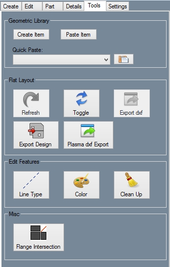
Using the tools tab, you can change the line type and color of features in both the Design View and the Flat Layout. There are a few other features in the Tools tab as well.
How-To
- Refresh: Refreshes the Flat Layout. If the Flat Layout is refreshed, any changes that you have made to it using the Tools tab will be lost.
- Toggle: Switches between the Design View and the Flat Layout.
- Export: Exports the Flat Layout as a .DXF file.
- Line Type: Select a line type in the Tool Bar and click the Line Type button in the Tools tab. Select a line to change its type. For information on selection, see the Selection and Features to Include pages.
- Color: Select a color in the Tool Bar. Click the Color button in the Tools tab and use a Selection feature of your choosing. If desired, you may also use the Features to Include function.
- Clean Up: Deletes any duplicate features or zero-length features.
- Flange Intersection: Click on the Flange Intersection button and click on two intersecting flanges.
Settings
Description
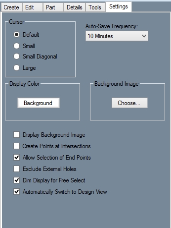
The Settings tab contains various options that can be used to customize interface.
Settings
- Cursor: Select either Default, Small, Small Diagonal, or Large to change the look of the cursor. Select each one and move the cursor over the display window to see what it looks like.
- Display Color: Click the Background button to change the background color of the display window using the Color menu.
- Background Image: To display an image in the background of the display window, click the Choose button and find a picture by using the windows file browser.
- Display Background Image: Toggles the display of a background image in the display window.
- Create Points at Intersections: Toggles the automatic creation of points at intersections between entities.
- Allow Selection of End Points: If this box is checked, end points of lines and arcs can be used as points for the placement of other features.
- Exclude External Holes: If this box is checked, holes that are not on a flange will be ignored.
- Dim Display for Free Select: Toggles the dimming of the display window when Free Select mode is active.
- Automatically Switch to Design View: Toggles the automatic switching to the Design View that occurs whenever the Design View is necessary for a function.


